ESD Car 2.0 - 3D Printing guide
Introduction and general information
The vehicle was developed using a Prusa MK3S+ (FDM/FFF) with a 0,4mm-nozzle. If you intend to use a different 3D printer, ensure that it is large enough to print the mountingPlate (226mm x 136mm).
If not stated otherwise, refer to the printer settings provided in the following table:
|
Setting |
Value |
|
material |
PETG |
|
infill |
5% |
|
layer height |
0,3mm |
|
support type |
organic |
In order to build the ESD Car, the following files are provided: step-files (3D-model), 3mf-slices (slicer) as well as gCode-files (printer), these can be found within the ESD Car DIY-Bundle.
Keep in mind, that the provided gCode-files only work for the previously described printer-setup and will need to be redone (sliced) for your specific setup.
If you need to generate your own gCode, make sure the orientation of those parts, as well as additional modifiers, etc. are the same as in the provided files. This is important due to two reasons:
the parts were designed with an specific orientation in mind to save supports
the mechanical properties depend on the printing-direction (anisotropy)
For post-processing or removing the supports of the parts, the following tools are useful:
small/sharp flat-head-screwdriver
small wire-cutters
general pliers
de-burring tool/utility knife
sandpaper (100 grid, although any is possible)
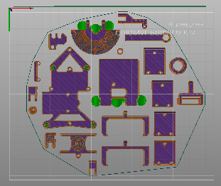
The following table provides an overview of the printing-files, together with the corresponding printing-times. Print them in the order of the table, so you can start the vehicle-assembly while printing.
|
|
File |
Hours |
Minutes |
|
1 |
complete_axle-beam-ends |
8 |
53 |
|
2 |
complete_driven-axle |
5 |
20 |
|
3 |
PCB-Stack 01 |
5 |
20 |
|
4 |
PCB-Stack 02 |
2 |
0 |
|
5 |
PCB-Stack 03 |
4 |
19 |
|
6 |
general mounts + tools |
5 |
26 |
|
7 |
vehicle stand + rims |
5 |
51 |
|
8 |
|
|
|
|
9 |
sum |
34 |
189 |
|
10 |
sum in hours |
37,15 |
|
Once you have completed this guide, move on to ESD Car 2.0 - Assembly of the vehicle.
Specific instructions
complete_axle-beam-ends
The step-file of the axle_beam-ends (both FL-RR and FR-RL) include 4 individual bodies. You may have to split the file into those bodies when importing it into your slicer.
The bearing seats, the rectangular slot of the axle_beam-ends as well as the "latchet" (see images) need support. Push out the bearing-supports with a screwdriver, other supports can be removed with pliers. Make sure an aluminium-extrusion can be pushed fully into the rectangular slot.
The bearing-seats of the axle-seats need supports. Push it out with a screwdriver, then scrape the bearing-seat with a flat-head-screwdriver to remove any leftover supports.
There exist different versions of the encoded axle-seat (axle_seatEncoded). Use the version 220 (22.0mm). The other versions change the "diameter of operation" of the encoder (refer to ESD Car 2.0 - Assembly of the vehicle).
The axle_seatEncoded also consists of multiple parts (main body, lid and shaft). Only the main body needs support (see image below). Make sure the encoder sits nicely (see ESD Car 2.0 - Assembly of the vehicle).
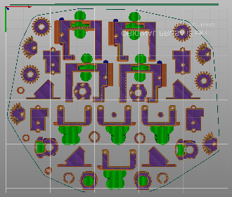
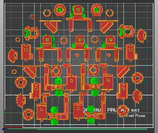
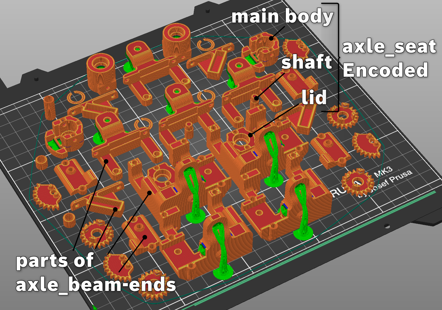
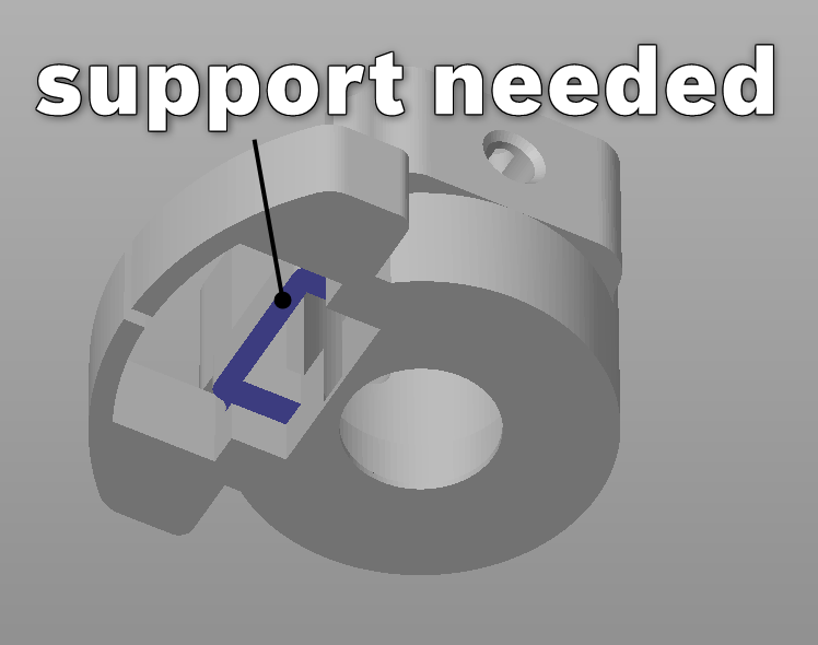
From left to right: Bottom view of whole 3mf-file, Top view of whole 3mf-file, Isometric view of the whole 3mf-file and close-up of the encoder-seat
Driven axle
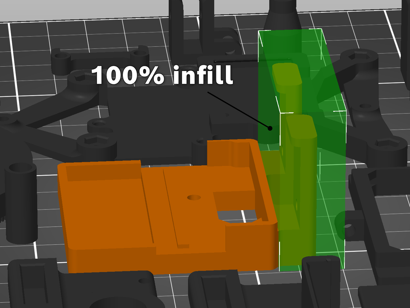
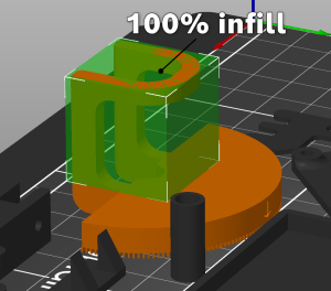
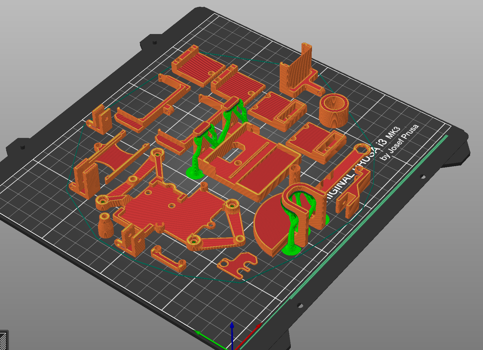
The cross_throughhole needs 100% infill and supports.
The housing_bevelgearbox-outerRing and housing_bevelgearbox-innerRing need support for the bearing-seat.
The gearbox_housing_motor_fullyPrinted and gearbox_housing_fullyPrinted need support for the bearing-seat.
The following parts need to be printed with perimeters set to 5:
gear_output-left
gear_output-motorSide
outputBevelGear_long
outputBevelGear_short
planetaryGear
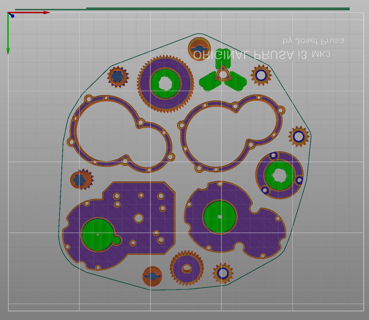
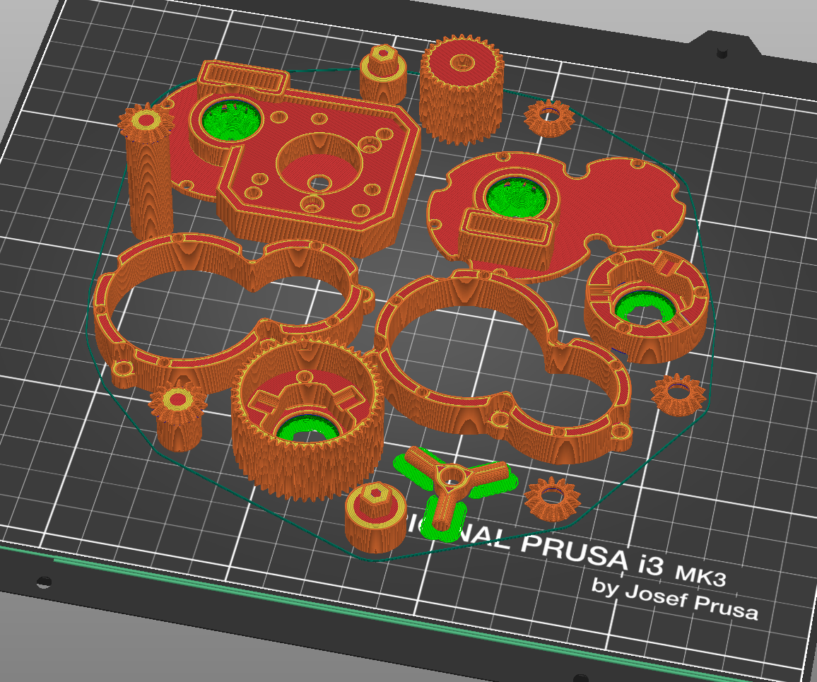
Left: Bottom-side of the 3mf-file "complete_driven-axle". Right: Isometric view
Post-processing
housing_bevelgearbox-outerRing: scrape out the whole bearing-seat with a flat-head screwdriver
housing_bevelgearbox-innerRing: scrape out the whole bearing-seat with a flat-head screwdriver
cross_throughhole: remove the supports and round off the "legs" with either sandpaper or by twisting it between the jaws of a pair of pliers
outputBevelGear_long: snip of any hanging filament-strands and clean up the underside of the teeth. If your printer tends to "elephant-foot", cut down the bottom of the shaft so it fits into the bearing
outputBevelGear_short: snip of any hanging filament-strands and clean up the underside of the teeth. If your printer tends to "elephant-foot", cut down the bottom of the shaft so it fits into the bearing
planetaryGear: clean out the bearing-seat
gearbox_housing_motor_fullyPrinted: clean the bearing-seat
gearbox_housing_fullyPrinted: clean the bearing-seat
PCB-Stack (PCB_baseplate_aluExtrusions)
The PCB_baseplate_aluExtrusions incorporates the following parts:
PCB_baseplate
PCB_topplate
PCB_topInsert
standoff Rasp (2 times)
mountingPlate
Your slicer might require to split the step-file of the PCB_baseplate_aluExtrusions to those individual parts.
The PCB-baseplate needs support at the USS-mounts as well as the "clamp"-portions of the plate. Make sure there aren't any residues on the bottom of the "clamps".
Only the clamps of the topInsert need support. Make sure there aren't any residues inside the clamps
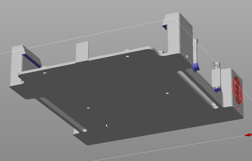
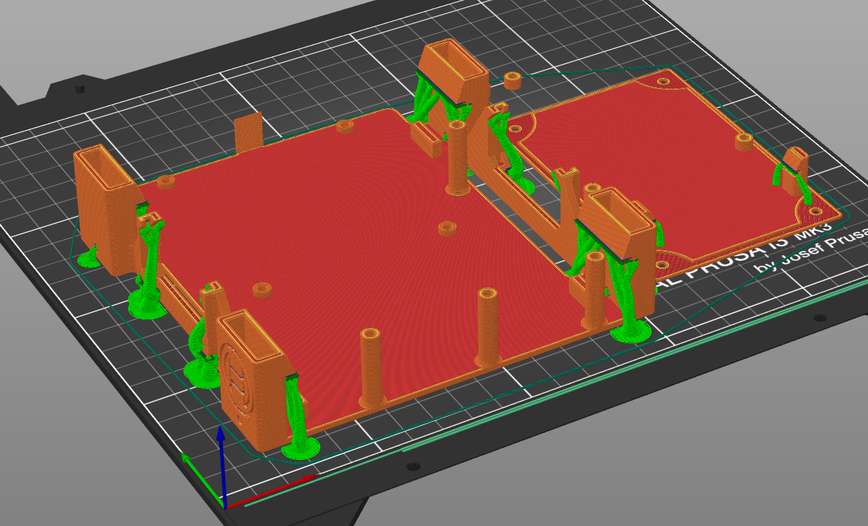
Left: Blue generates supports, red blocks supports, Right: Sliced PCB-baseplate and topInsert
The PCB-topplate, mountingPlate, vehicle-stand and rims don't need any support. Nonetheless remove any loose strands of filament from the rims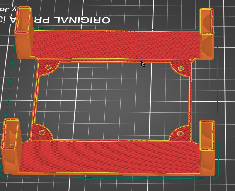
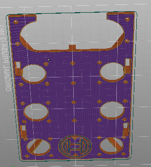
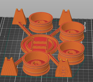
Left: topplate, center: mountingPlate, right: vehicle-stand and rims
Mounts and tools
The combined LIDAR and gyro mount (combinedLIDAR_gyro) need support for the bottom side of its hexagonal holes. It also needs to be split into its three parts:
main mount
gyroscope strap
LIDAR PCB strap
The baseplate of the accu_connector needs support for its "prongs". Those prongs also need to be printed with 100% infill.
The wheel_calibrationScale needs support and 100% infill for its legs.