ESD Car 2.0 - Bill of materials for electrical buildup
Tools
For building up the electronics y ou can decide whether you want to manufacture the PCBs yourself (using CNC milling or chemical etching), or if you like to choose an online-service to manufacture them (search for "PCB service").
Additionally following tools are useful:
Soldering Iron: Essential for connecting components on a circuit board.
Solder: High-quality solder makes soldering easier.
Side Cutters: Used for cutting wires and component leads.
Crimping Pliers: For JST-XC contacts, used for attaching connectors to wires securely.
Screwdrivers: For assembling connectors, enclosures and other mechanical parts.
Desoldering Pump or Wick: In case you need to correct mistakes.
Multimeter: Measures voltages, currents, and resistances.
Third Hand: Holds the board steady during soldering.
PCB Holder: Prevents the board from slipping.
Soldering Mat or Fireproof Surface: Protects your table from heat.
Magnifying Glass or Loupe: Helpful for small components.
PCB Designs
The schematics and PCBs are designed with KiCad (V 7.0) and are available as projects for each board, and are available within the ESD Car DIY-Bundle.
Car2.0_DcDcBoard
Features:
Powersupply 18V to 5V (5,1V - 5,6V) adjustable
Powersupply 18V to 3,3V
Reset of Sensor/Device-Supply
DcDcBoard - 3D View:
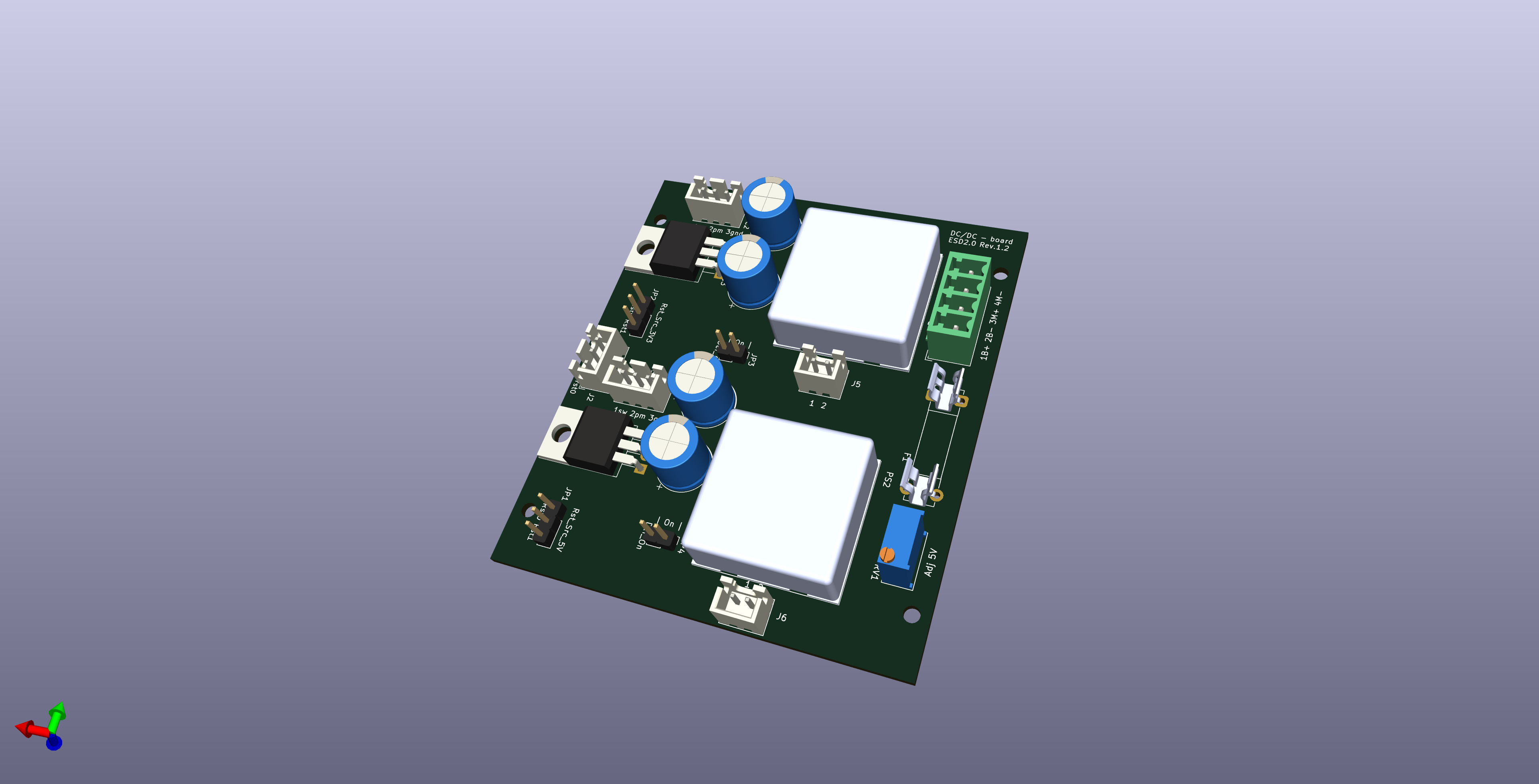
Schematics: Car2.0_DcDcBoard.pdf
BOM:
|
Part |
Description |
Order-Nr |
Alternative |
|
J1 |
Terminal Block, Header, 3.81 mm, 4 Ways, 10 A, 300 V, Through Hole Vertical |
824-6611 220-4850 |
691321300004 1803442 |
|
PS1 |
CCG30-24-03S (DCDC-Converter 3,3V) |
2531637 899-8491 |
CCG30-24-03S |
|
PS2 |
CCG30-24-05S (DCDC-Converter 5V) |
2531638 899-8501 |
CCG30-24-05S |
|
Q1, Q2 |
BSS138BK Power-MOSFET, n-Kanal, 60 V, 360 mA, 1 ohm, SOT-23, Through Hole mount |
BSS138BK |
4140856 792-0894P |
|
RV1 |
BOURNS 3296W-1-104LF Trimmer-Potentiometer, 100kΩ |
3296W-1-104LF PV36W104C01B00 |
9353194 769-2160 |
|
Q3, Q4 |
P-Kanal, THT MOSFET 30 V / 80 A 137 W, 3-Pin TO-220 |
823-5554 |
IPP80P03P4L04AKSA1 |
|
C1-4 |
Polymerkondensator 150μF ±20% 35V |
870055675010 |
839-2344 |
|
J5, J6 |
Pin Header, Vertical, Wire-to-Board, 2.5 mm, 1 Rows, 2 Contacts, JST XH |
B2B-XH-A(LF)(SN) |
820-1554 1516276 |
|
J2-4 |
Pin Header, Vertical, Wire-to-Board, 2.5 mm, 1 Rows, 3 Contacts, JST XH |
B3B-XH-A(LF)(SN) |
820-1557 1516277 |
|
R1, R2, R9, R10 |
Resistor 1K SMD:R_0805 |
|
|
|
R3, R5 |
Resistor 220K SMD:R_0805 |
|
|
|
R4, R6 |
Resistor 470K SMD:R_0805 |
|
|
|
R7, R8 |
Resistor 20K SMD:R_0805 |
|
|
|
R11 |
Resistor 12K SMD:R_0805 |
|
|
|
JP5, JP6, JP7 |
Resistor 0K SMD:R_0805 (optional, depending on configuration, see hints in schematic) |
|
|
|
F1 |
Fuse 5A |
|
563-532 |
|
F1 |
Fuse holder |
01110501Z |
876-7833 |
Car2.0_AdapterBoard (Pico-Board)
Features:
RPI Pi Pico carrier
Reset-Interface
Debug/Serial Interface
TTL 3V3/5V converter on inputs
2x I2C Interfaces with selectable voltage
4x USS interfaces with selectable voltage
1x Two Channel Quadrature input
4x Servo control
Stepper control
AdapterBoard (Pico-Board) - 3D View:
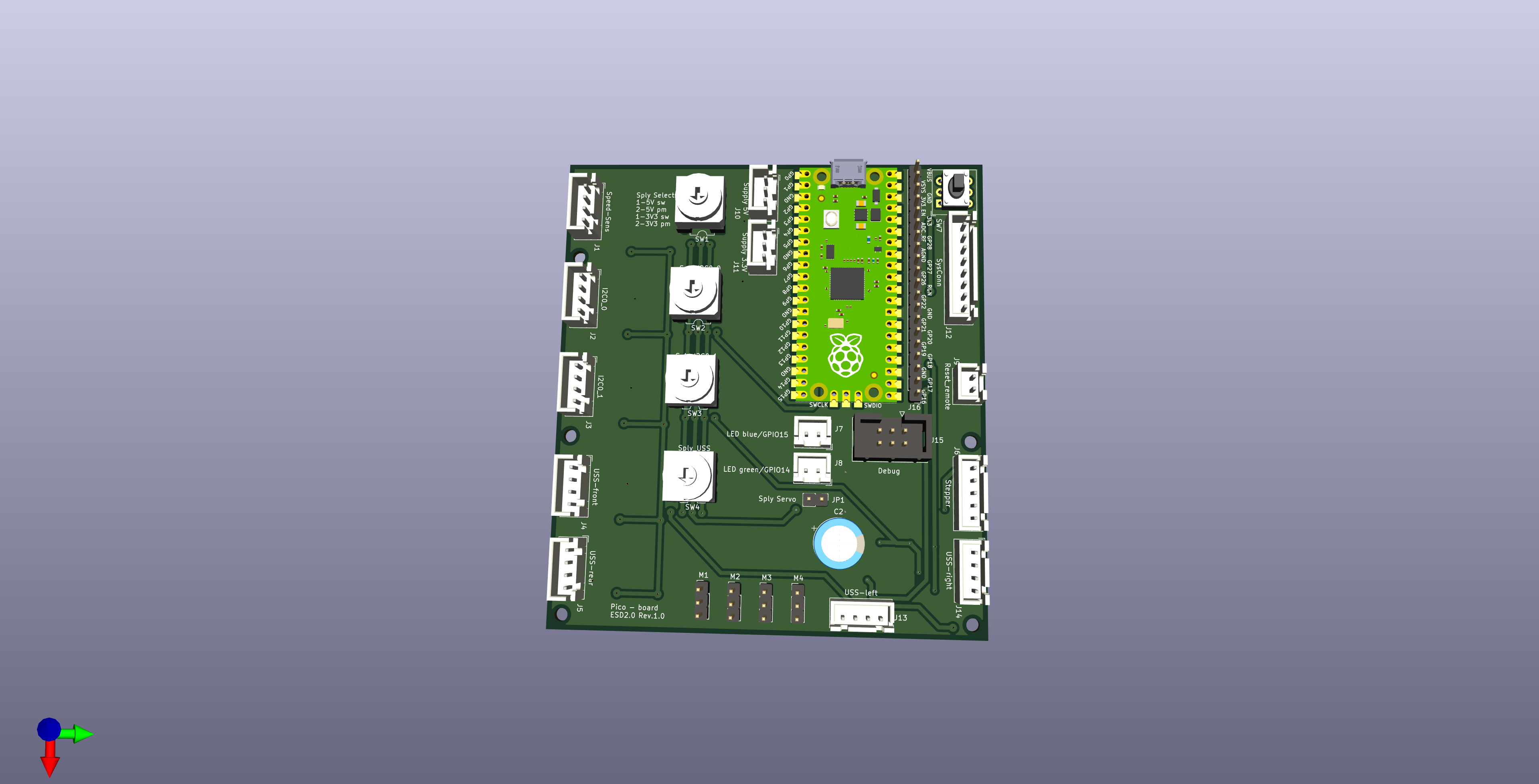
Schematics: Car2.0_AdapterBoards_v1.1.pdf
BOM:
|
Part |
Description |
Order-Nr |
Alternative-Nr |
|
SW1-SW4 |
Rotary switch, 4 positions, 1-polig, 36 °, S-2050 |
S-2050 |
2979787 |
|
Q15 |
Mosfet DMG2305UX |
||
|
Q1-Q14 |
14x 10kMosfet BSS138BK |
||
|
C2 |
Polymerkondensator 150μF ±20% |
870055675010 |
839-2344 |
|
C1, C3, C5, C7 |
4x Kondensator 100nF SMD |
264-4416 1414664 |
C0805C104K5RACTU |
|
R1-R24, R26-R29 |
28x Resistor 10K SMD:R_0805 |
ERJUP6F1002V |
243-2234P |
|
R25 |
Resistor 2K2 SMD:R_0805 |
ERJUP6F2201V |
243-2278 |
|
U1 |
RPI Pico |
SC0916 |
212-2162 |
|
U1-Connector, J16 |
3x Pinheader 20pin (1 Row) |
61302011121 |
828-1639 |
|
|
2x PCB Receptacle, Board-to-Board, 20 Contacts |
|
|
|
U1-Connector Dbg, J15 |
1x Stiftleiste / Pinheader 6Pin (2 Rows x03pin) |
251-8137 |
|
|
J1-J5, J13,J14 |
7x Pin Header, Vertical, Wire-to-Board, 2.5 mm, 1 Rows, 4 Contacts, JST XH |
820-1551 1516278 |
B4B-XH-A(LF)(SN) |
|
J7-J9 |
3x Pin Header, Vertical, Wire-to-Board, 2.5 mm, 1 Rows, 2 Contacts, JST XH |
820-1554 1516276 |
B2B-XH-A(LF)(SN) |
|
J10, J11 |
2x Pin Header, Vertical, Wire-to-Board, 2.5 mm, 1 Rows, 3 Contacts, JST XH |
820-1557 1516277 |
B3B-XH-A(LF)(SN) |
|
J6 |
1x Pin Header, Vertical, Wire-to-Board, 2.5 mm, 1 Rows, 5 Contacts, JST XH |
820-1560 1516281 |
B5B-XH-A(LF)(SN) |
|
J12 |
1x Pin Header, Vertical, Wire-to-Board, 2.5 mm, 1 Rows, 8 Contacts, JST XH |
820-1576 1516284 |
B8B-XH-A(LF)(SN) |
|
JP1 |
1x Stiftleise / Pinheader 2Pin (1 Rows) + Jumper (optional) |
251-8086 |
|
|
M1-M4 |
4x Stiftleise / Pinheader 3Pin (1 Rows) |
360-6320 |
90120-0763 |
|
SW7 |
Reset-Switch |
2473074 |
3ETH9-15.0 |
Gyro/IMU Board
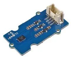
|
Part |
Description |
Order-Nr |
Alternative-Nr |
|
Gyro/IMU Board |
SEEED STUDIO 101020584 - Sensorplatine, BMI088, 6-Achsen-Trägheitssensor |
101020584 |
4200154 |
Car2.0_stepper
Features:
2 phase stepper control TMS2209
with control Interface and UART calibration interface
Stepper board - 3D view:
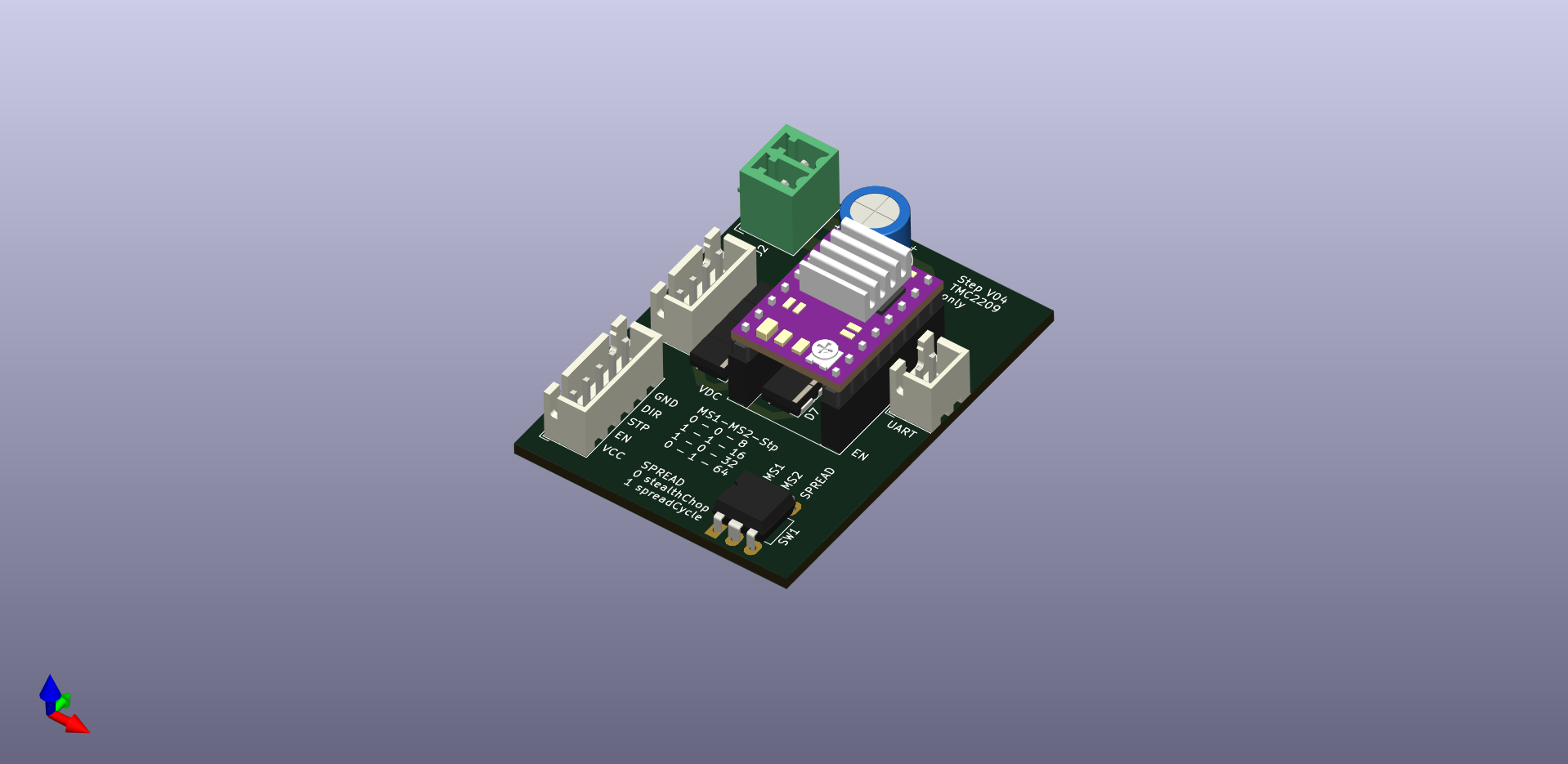
Schematics: Stepper_Driver_Board.pdf
DIP-Switch-Setting
Set the DIP-switch to the following positions:
|
# |
Setting |
On/Off |
|
1 |
MS1 |
On |
|
2 |
MS2 |
On |
|
3 |
SPREAD |
Off |
Like shown in the following picture:
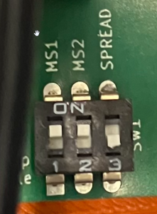
This settings are relevant for the proper velocity of the vehicle. Internal default parameters for driving are configured according to these settings.
BOM:
|
Part |
Description |
Order-Nr |
Alternative |
|
J2 |
Terminal Block, Header, 3.81 mm, 2 Ways, 10 A, 300 V, Through Hole Vertical |
824-6614 220-4822 897-1105 |
691321300002 1803426 |
|
J3 |
Pin Header, Vertical, Wire-to-Board, 2.5 mm, 1 Rows, 4 Contacts, JST XH |
820-1551 1516278 |
B4B-XH-A(LF)(SN) |
|
J1 |
Pin Header, Vertical, Wire-to-Board, 2.5 mm, 1 Rows, 5 Contacts, JST XH |
820-1560 1516281 |
B5B-XH-A(LF)(SN) |
|
J4 |
Pin Header, Vertical, Wire-to-Board, 2.5 mm, 1 Rows, 2 Contacts, JST XH |
820-1554 1516276 |
B2B-XH-A(LF)(SN) |
|
D1-D9 |
9x STPS5L60 Schottky-Gleichrichterdiode, 60 V, 5 A, Einfach, DO-214AA (SMB), 2 Pin(s), 520 mV |
233-3095 2522891RL |
STPS5L60U |
|
A1 |
Evaluationsboard, TMC2209 SilentStepStick, 2-Phasen-Motortreiber TRINAMIC / ANALOG DEVICES TMC2209 SILENTSTEPSTICK |
3131532 |
TMC2209 SILENTSTEPSTICK |
|
SW1 |
DIP-/SIP-Switch, 3 Schaltkreis(e), Schiebeschalter, Durchsteckmontage |
877-2179 1523985 |
IKD0300101 MCEI-03 |
|
C1 |
Polymerkondensator 150μF ±20% 35V |
870055675010 |
839-2344 |
|
C2 |
Kondensator 100nF SMD |
264-4416 1414664 |
C0805C104K5RACTU |
|
A1 |
cooler, for SMD-parts, 6.3 mm, 4.8 mm, 17 mm |
4302205 504-0722 |
ICK SMD A 17 SA ICKSMDA13 |
|
A1 |
2x Pin header vertical 8-pins |
765-5705 1668367 |
SSW-108-02-G-S |
RPI5_header
Features:
RPI5 Power supply
EEPROM for HAT-identification
Reset control for RPI-Pico
RPI5_header board - 3D view:
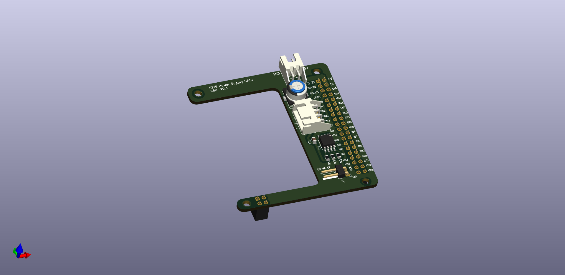
Schematics: RPI5_header_board.pdf
BOM:
|
Part |
Description |
Order-Nr |
Alternative |
|
J1 |
40-Pin Header extra long pin |
M20-6102045 |
1569230 681-6794 |
|
J2 |
JST_XH_S2B-XH-A_1x02 |
S2B-XH-A(LF)(SN) |
820-1582 1516289 |
|
J3 |
JST_XH_S4B-XH-A_1x04 |
S4B-XH-A(LF)(SN) |
820-1589 1516291 |
|
J4 |
PinHeader_1x02_P2.54mm_Horizontal |
61300211021 |
828-1651 2356176 |
|
J5 |
PinSocket_2x02_P2.54mm_Vertical |
M20-7830246 |
7991975 681-6839 |
|
R1,R2 |
Resistor 3K9 SMD:R_0805 |
|
804-6492 |
|
R3 |
Resistor 1K SMD:R_0805 |
|
713-6939 |
|
C1 |
Capacitor 100nF, SMD:C_0805 |
08051C104K4T4A C0805C104J4JACAUTO |
4229612 3954053 264-4416 |
|
C2,C3 |
Capacitor 100uF polarized, SMD or radial choose one item |
SMD: MCVKZ016M101FB3L radial: |
2611331 747-2875P 2575608 449-1056P |
|
U1 |
EEPROM, 64 Kbit, 8K x 8 Bit, Seriell I2C, SOIC, 8 Pin(s) |
M24C64-RMN6P |
387-354P 3130120 |
RPI5
BOM:
|
Part |
Description |
Order-Nr |
Alternative |
|
RPI5 |
RASPBERRY-PI RPI5-8GB |
RPI5-8GB-SINGLE |
4256000 |
|
Cooler |
RASPBERRY-PI SC1148 |
SC1148 |
4263049 |
|
SD-Card |
microSD-Card Min. 64GB, >150MB/s Read > 80MB/s Write |
|
|
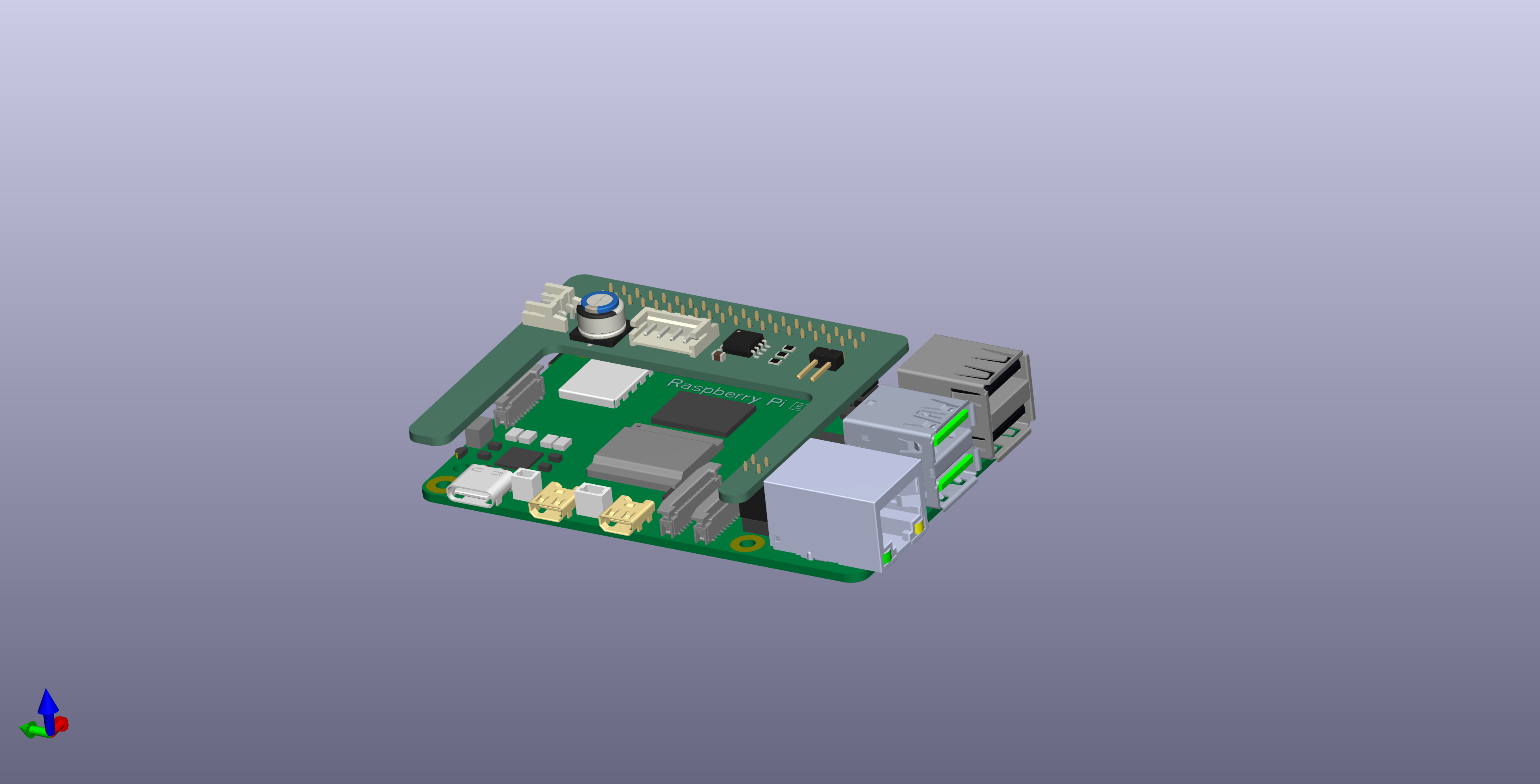
RPI5_header setup
Just mount the RPI5_header on TOP of the RPI5:
Lidar Setup
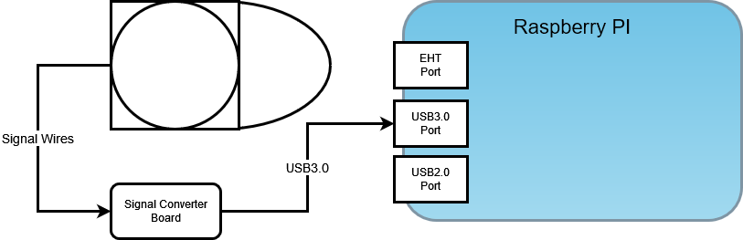
DIP-Switch-Setting
To provide enough power to the Lidar it needs to be connected on USB3.0 port
Sensors
USS (Ultrasonic Sensor)
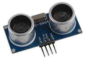
Specification:
Type: HC-SR04
Operating Voltage 3-5V
Measuring Distance: 0,02-4m
BOM
|
Part |
Description |
Order-Nr |
Alternative |
|
USS |
4x HC-SR04 |
PSG04177 |
4162011 215-3181 |
LIDAR
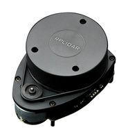
Specification:
Model: RPLIDAR A1M8-R6
Distance Range: 0.15-12m
Angular Range: 0-360 degree
Distance Resolution: <0.5mm /<1% of the distance (All distance range)
Angular Resolution: ≤1 degree
Sample Duration: 0.125 millisecond
Sample Frequency: ≥ 8000Hz
Scan Rate: 5.5Hz
Weight: 170g
BOM
|
Part |
Description |
Order-Nr |
Alternative |
|
Lidar |
DFROBOT DFR0315 DEV KIT, 360ø-LASERSCANN |
DFR0315 |
e-3517894 |
Speed Sensor
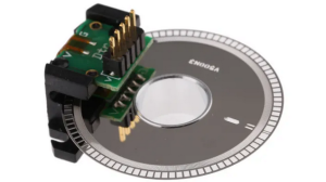
Features:
Two Channel Quadrature Output with Index Pulse
Resolution 500 CPR (Counts Per Revolution)
TTL Compatible
Single 5V Supply
BOM:
|
Part |
Description |
Order-Nr |
Alternatives |
|
Speed Sensor |
Broadcom Optischer Drehgeber Encoder 5V dc |
AEDB-9140-A13 |
796-7806 1161087 |
Camera (optional)
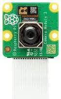
|
Part |
Description |
Order-Nr |
Alternative |
|
Camera |
Raspberry Pi Camera Module 3, 3MP, IMX708, Raspberry Pi-Computer |
SC0872 |
4132318 |
Actors
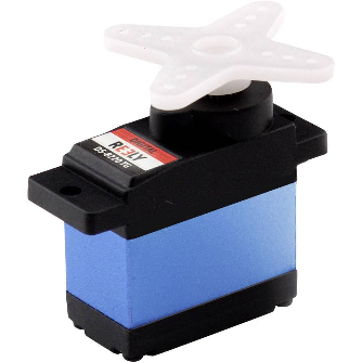
Servos
|
Part |
Description |
Order-Nr |
Alternative |
|
Servo |
4x Reely DS8220 |
RE-6679761 |
|
Specification :
Model: DS-8220 TG
Dim (L x W x H): 23 x 12 x 25 mm
Length: 23mm
Width: 12mm
Height: 25mm
Weight: 13g
Servo torque (4.8 V)12Ncm
Servo torque at 6 V15Ncm
Actuation time at 4.8 V0.12 s (60°)
Actuation time at 6 V0.10 s (60°)
Gear boxTitanium
Type of bearingBall bearing
Servo technologyDigital servo
Connector systemJR
VoltageLow
Manufacturer part #RE-6679761
Min. operating voltage: 4.8V
Operating voltage: 4.8 - 6 V
Max. operating voltage: 6V
Plastic free packaging: Plastic-free packaging
Product type: Mini servo
Stepper-Motor
|
Part |
Description |
Order-Nr |
Alternative |
|
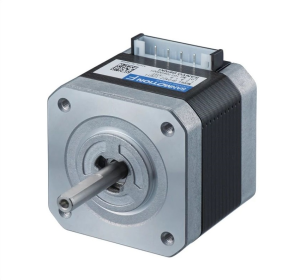
Motor |
Sanyo Denki SF242 Hybrid 1.8° Schrittmotor 24 V / 1 A 0.29Nm 4-adrig, 42 x 42mm Wellen-Ø 5mm |
SF2421-10B41 |
183-3580 3052028 |
Power Supply
|
Part |
Description |
Order-Nr |
Alternative |
|
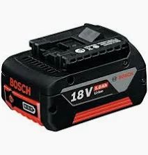
Battery |
Bosch GBA Li-Ion Werkzeug Akku, 18V / 5Ah |
4037987 |
2607337070 |
Wiring
Connectors
|
Item |
Description |
Order-Nr |
Alternative |
|
|
1x |
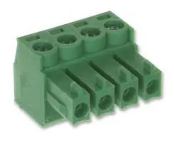
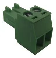
Terminal Block Connector, 4 Contacts, 3.81mm Pitch, Straight (KB 4p 3.81mm) |
825-0830 220-4670 144-4285 |
691361300004 1803594 |
|
|
2x |
Terminal Block Connector, 2 Contacts, 3.81mm Pitch, Straight (KB 2p 3.81mm) |
825-0828 220-4658 144-4337 |
691361300002 1803578 |
|
|
7x |
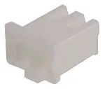
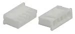
JST XHP Connector Housing Socket, 2.5mm, 2-pin (JST-XHP-2) |
820-1611 1516264 |
XHP-2 |
|
|
5x |
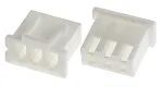
JST XHP Connector Housing Socket, 2.5mm, 3-pin (JST-XHP-3) |
820-1614 1516265 |
XHP-3 |
|
|
10x |
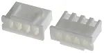
JST XHP Connector Housing Socket, 2.5mm, 4-pin (JST-XHP-4) |
820-1618 1516266 |
XHP-4 |
|
|
2x |
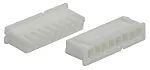
JST XHP Connector Housing Socket, 2.5mm, 5-pin (JST-XHP-5) |
820-1627 1516268 |
XHP-5 |
|
|
1x |
JST XHP Connector Housing Socket, 2.5mm, 8-pin (JST-XHP-8) |
820-1633 1516271 |
XHP-8 |
|
|
|
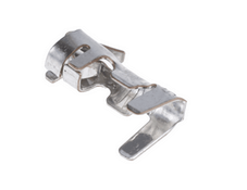
JST XH Crimp Terminal for XH Connector Housing |
820-1529 1516301 |
BXH-001T-P0.6 |
|
|
1x Speed Connector |
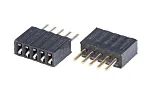
PCB Socket, Straight, 5-pin / Single Row, 1.27mm Pitch |
681-3023 1099543 |
M52-5000545 |
|
|
Speed Connector Alternative |
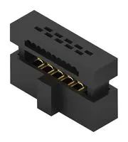
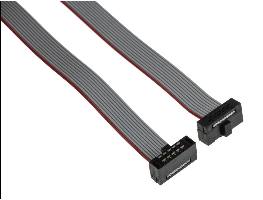
IDC Connector, Right-Angle, IDC Socket, Female, 1.27mm, Single Row, 5 Contacts, Cable Mount IDC Connector, IDC Socket, Female, 1.27mm, Dual Row, 10 Contacts, Cable Mount Ribbon Cable, IDC Socket to Free End, 10-pin, 12", 305mm, 1.27mm, Tiger Eye FFSD |
524431-E 62701023121 |
4060517 3818517 2856053 |
|
Wiring the cables
ActuatorPicoPCB2LedBlue
Usage
Connects to J7 on Pico-board (GP15). Currently used for status indication.
Diagram

Reading the wiring-diagrams
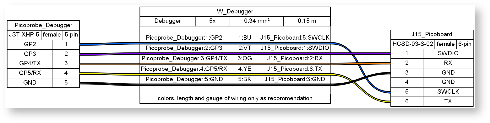
The wiring-diagrams displayed in this section were created with the open source tool WireViz (https://github.com/wireviz/WireViz).
There are two types of boxes:
connector & part-boxes
wire-boxes
Connector-boxes and part-boxes have colored cables run from their ends, in the figure above, e.g. J7_LedBlue and W_LedBlue. The needed information for wiring is written inside them respectively.
Wire-boxes describe the cables, which run through it. If multiple cables run through it, they all share the same properties (except the color and possibly connection-points), e.g. W_LedBlue1.
The left-most box (J7_LedBlue) is a connector/-part-box. In this case, it is a male 2pin-plug of the type JST-XHP-2. It will get connected to GP15 and GND on the Pico-board. The two cables (colored paths) run through the wire-box W_LedBlue1 and thus both are 0.15m long and of the same area. The blue one gets connected to the first leg of Resistor47R (own box), the other leg gets connected, via a wire (W_LedBlue2) to the Anode (noted with A) of a blue LED (LedBlue).
BOM
|
Description |
Qty |
Unit |
Designators |
|
Cable, 1 x 0.34 mm² |
0.01 |
m |
W_LedBlue2 |
|
Cable, 2 x 0.34 mm² |
0.15 |
m |
W_LedBlue1 |
|
Connector, JST-XHP-2, male, 2 pins |
1 |
|
J7_LedBlue |
|
LedBlue, male, 2 pins |
1 |
|
LedBlue |
|
Connector, Resistor47R, male, 2 pins - check if resistance appropriate for your LED! |
1 |
|
Resistor47R |
ActuatorPicoPCB2LedGreen
Usage
Connects to J8 on Picoboard (GP14). Currently used for status indication.
Diagram

BOM
|
Description |
Qty |
Unit |
Designators |
|
Cable, 1 x 0.34 mm² |
0.01 |
m |
W_LedGreen2 |
|
Cable, 2 x 0.34 mm² |
0.15 |
m |
W_LedGreen1 |
|
Connector, JST-XHP-2, male, 2 pins |
1 |
|
J8_LedGreen |
|
LedGreen, male, 2 pins |
1 |
|
LedGreen |
|
Connector, Resistor47R, male, 2 pins - check if resistance appropriate for your LED! |
1 |
|
Resistor47R |
Actuator_PicoPCB2Servo (optional)
Usage
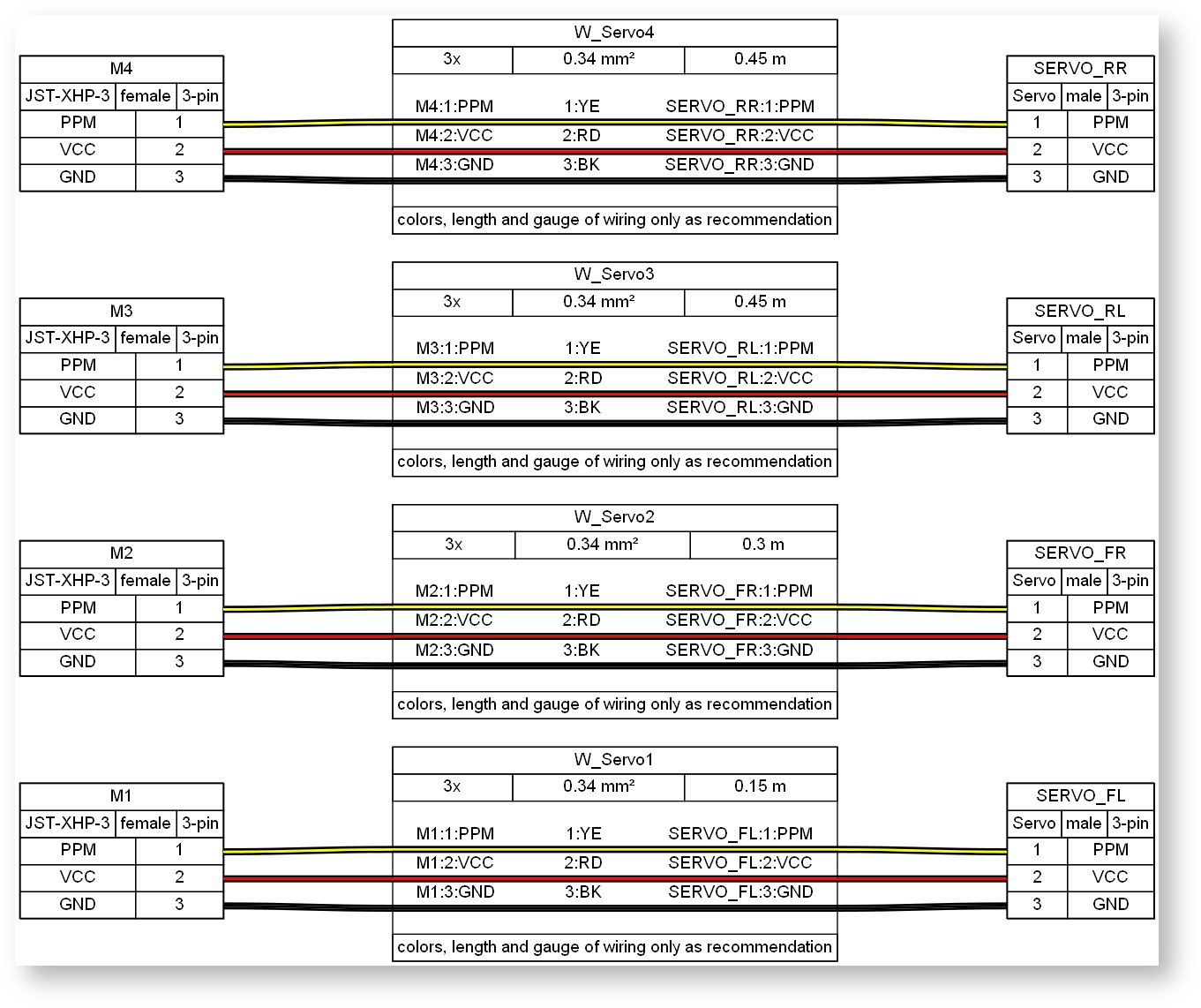
Connects M1-M4 on the Picoboard to the four steering-servos. Normally delivered attached to the servo, therefore optional.
Diagram
BOM
|
Description |
Qty |
Unit |
Designators |
|
Cable, 3 x 0.34 mm² |
1.35 |
m |
W_Servo1, W_Servo2, W_Servo3, W_Servo4 |
|
Connector, JST-XHP-3, female, 3 pins |
4 |
|
M1, M2, M3, M4 |
|
Connector, Servo, male, 3 pins |
4 |
|
SERVO_FL, SERVO_FR, SERVO_RL, SERVO_RR |
Actuator_StepperPCB2Motor
Usage
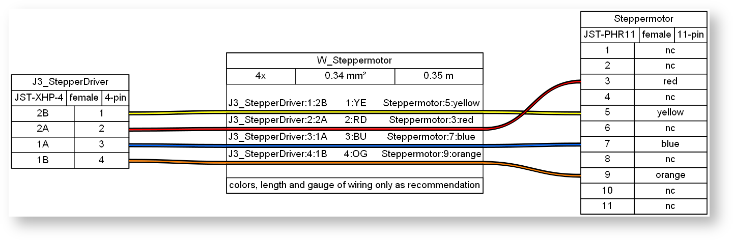
Connects J3 of the stepperdriver-board to the stepper-motor.
This cabling is validated only with the stepper motor (Sanyo Denki SF242)
Diagram
BOM
|
Description |
Qty |
Unit |
Designators |
|
Cable, 4 x 0.34 mm² |
0.35 |
m |
W_Steppermotor |
|
Connector, JST-PHR11, female, 11 pins |
1 |
|
Steppermotor |
|
Connector, JST-XHP-4, female, 4 pins |
1 |
|
J3_StepperDriver |
Debugger_Picoprobe2PicoPCB
Usage
Connection of a Picoprobe-Debugger to the Picoboard for flashing and debugging.
Solder a 2,54mm - pinheader/5-pins on GP2-GP5, GND (Pico pins 4-8) of the Pico that is used as Picoprobe-Debugger.
Diagram
BOM
|
Description |
Qty |
Unit |
Designators |
|
Cable, Debugger, 5 x 0.34 mm² |
0.15 |
m |
W_Debugger |
|
Connector, HCSD-03-S-02, female, 6 pins |
1 |
|
J15_Picoboard |
|
Connector, JST-XHP-5, female, 5 pins |
1 |
|
Picoprobe_Debugger |
Logic_PicoPCB2RpiHeaderPCB
Usage
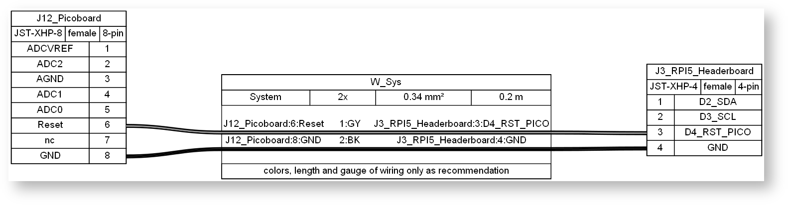
Currently used only to connect the reset-pin of the Picoboard to the RaspberryPi.
Diagram
BOM
|
Description |
Qty |
Unit |
Designators |
|
Cable, System, 2 x 0.34 mm² |
0.2 |
m |
W_Sys |
|
Connector, JST-XHP-4, female, 4 pins |
1 |
|
J3_RPI5_Headerboard |
|
Connector, JST-XHP-8, female, 8 pins |
1 |
|
J12_Picoboard |
Logic_PicoPCB2StepperPCB
Usage
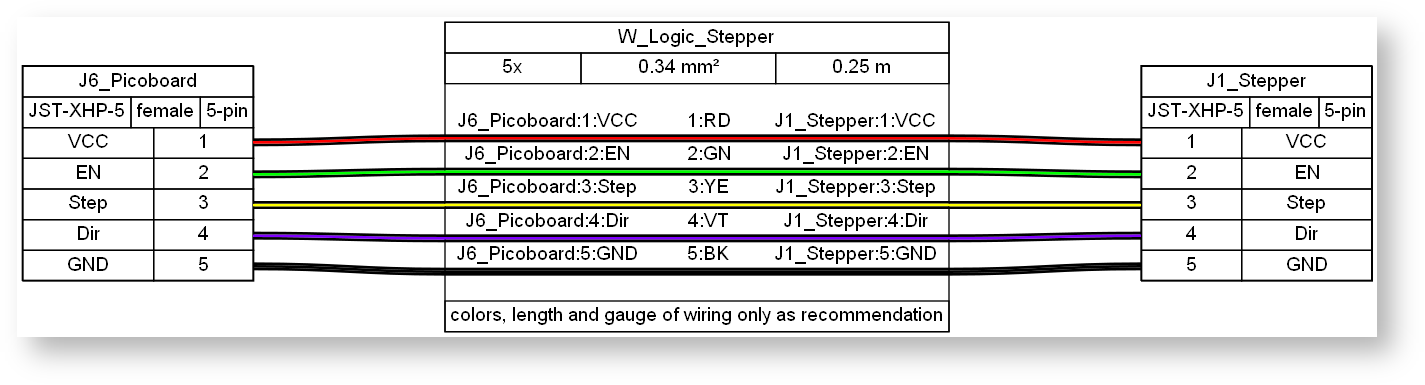
Connects J6 of the Picoboard to the StepperPCB to provide the logic-signals for motorcontrol.
Diagram
BOM
|
Description |
Qty |
Unit |
Designators |
|
Cable, 5 x 0.34 mm² |
0.25 |
m |
W_Logic_Stepper |
|
Connector, JST-XHP-5, female, 5 pins |
2 |
|
J1_Stepper, J6_Picoboard |
Sensor_PicoPCB2Gyro
Usage
I2C-connection from Pico-board/J2 to the gyro sensor.
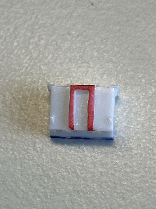
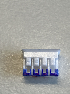
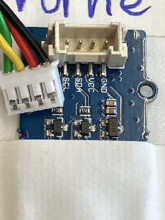
The SeedStudio-Gyrosensor uses a proprietary connector (TWIG-4P-2.0). Since no source for the bare connector could be found, there are two possibilities to wire the gyro sensor: 1) Purchasing a prewired cable with the TWIG-connector and complete it with the JST-XHP-4 connector, 2) Manufacture the cable described in this chapter, using a mechanically modified JST-PH 2.0mm connector as shown below - coding-latches (marked red) and the lower part of the connector-housing opposite to the coding-latches (marked blue) need to be trimmed (recommended).
Diagram

BOM
|
Description |
Qty |
Unit |
Designators |
|
Cable, Gyro, 4 x 0.34 mm² |
0.3 |
m |
W_Gyro |
|
Connector, JST-XHP-4, female, 4 pins |
1 |
|
J2 |
|
Connector, TWIG-4P-2.0 or modified JST-PH-4 2.0mm, female, 4 pins |
1 |
|
Gyro |
Sensor_PicoPCB2Speed
Usage
Connect the odometry-sensor to J1 of the Pico-board.
This cable has to be as flexible as possible, hence take care of the limited space on the encoder's side when fitting the IDC-connector to the cable.
Diagram

BOM
|
Id |
Description |
Qty |
Unit |
Designators |
|
1 |
Cable, 4 x 0.1 mm² |
0.35 |
m |
W_Speed_Sens |
|
2 |
Connector, IDC 5pin 1,27mm, female, 5 pins |
1 |
|
Speed_Sens |
|
3 |
Connector, JST-XHP-4, female, 4 pins |
1 |
|
J1_Speed |
Sensor_PicoPCB2USS
Usage
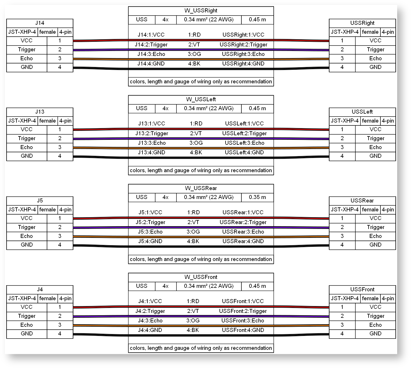
Connect J4, J5, J13, J14 to the ultrasonic-sensors.
Left and right USS-sensors are optional and currently not implemented in the software, hence cable them accordingly.
Diagram
BOM
|
Description |
Qty |
Unit |
Designators |
|
Cable, USS, 4 x 0.34 mm² |
1.7 |
m |
W_USSFront, W_USSLeft, W_USSRear, W_USSRight |
|
Connector, JST-XHP-4, female, 4 pins |
8 |
|
J13, J14, J4, J5, USSFront, USSLeft, USSRear, USSRight |
Supply_Battery2DcDcPCB
Usage
Mainsupply-cable to connect the battery to the DC/DC-converterboard.
Diagram

BOM
|
Description |
Qty |
Unit |
Designators |
|
Cable, Battery-Supply, 2 x 1 mm² |
0.25 |
m |
Battery_to_System |
|
Connector, Custom adapter (accu_blade_slotted) , fixed cable, 2 pins |
1 |
|
Battery |
|
Connector, WR-TBL 3,81mm, male, 2 pins |
1 |
|
J1_DCDC |
Supply_DcDcPCB2PicoPCB
Usage
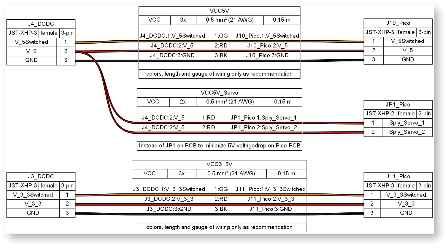
Supply both 3,3V and 5V from the DC/DC-Board (J3, J4) to the Pico-board (J11, J10).
Both supplies 5V and 3,3V could be provided with the same cable-type using only three wires. Nevertheless, to minimize the voltagedrop on the 5V-supply when actuating all servos, it is strongly remommended to route two additional 5V-wires to the Pico-board, with the JST-XHP-2-connector replacing the jumper JP1 on the board.
Diagram
BOM
|
Description |
Qty |
Unit |
Designators |
|
Cable, VCC, 2 x 0.5 mm² |
0.15 |
m |
VCC5V_Servo |
|
Cable, VCC, 3 x 0.5 mm² |
0.3 |
m |
VCC3_3V, VCC5V |
|
Connector, JST-XHP-2, female, 2 pins |
1 |
|
JP1_Pico |
|
Connector, JST-XHP-3, female, 3 pins |
4 |
|
J10_Pico, J11_Pico, J3_DCDC, J4_DCDC |
Supply_DcDcPCB2RpiHeaderPCB
Usage
Supply Batteryvoltage/power from the DC/DC-Board (J1) to the RPi via the RPi5-Headerboard.
RPi5 needs the 5V-supply to be trimmed to be about 5,2-5,3V, see instructions concerning the DC/DC-PCB.
To ensure stable supply of the RPI5 use wiring with maximum gauge that fits the connectors, additional soldering of the crimped connectors is recommended.
Diagram

BOM
|
Description |
Qty |
Unit |
Designators |
|
Cable, Supply, 2 x 0.5 mm² |
0.25 |
m |
W_SplyRPI |
|
Connector, JST-XHP-2, female, 2 pins |
2 |
|
J2_RPI5_Headerboard, J6_DCDC |
Supply_DcDcPCB2StepperPCB
Usage
Supply Batteryvoltage/power from the DC/DC-Board (J1) to the motordriver on StepperPCB (J2).
Diagram

BOM
|
Description |
Qty |
Unit |
Designators |
|
Cable, Battery-Supply, 2 x 1 mm² |
0.25 |
m |
Battery_DCDC_to_StepperDriver |
|
Connector, WR-TBL 3,81mm, male, 2 pins |
2 |
|
J1_DCDC, J2_StepperDriver |