ESD Car 2.0 - Assembly of the vehicle
Tools
You will need the following tools:
Hex-Key 2.0mm
Pair of pliers
Size 7 hex-nut/size 7 wrench
Metal saw
File/sand paper
small desktop-vice (not strictly necessary but strongly recommended)
The following tools can be printed:
Bearing press 21mm
Bearing press 10mm-7mm
Press code-wheel Axis
Preparation
BOM and printing-instructions
Prepare all components based on: ESD Car 2.0 - Bill of materials for mechanical assembly & ESD Car 2.0 - Bill of materials for electrical buildup.
Read the printing guide: ESD Car 2.0 - 3D Printing guide - there it is also described how to remove supports/prepare the printed parts for assembly.
Aluminium-Beams
Before you can start with the actual guide, cut the aluminium beams (20x5) to lengths. After cutting, clean up the edges with a file and smooth out the sawed surfaces. There exist an stencil to support the cutting-process.
Tolerance: -1mm
|
name |
length per beam |
beams needed |
length combined |
|
cha_beam_l |
250 |
2 |
500 |
|
ab_l_short |
37,7 |
1 |
37,7 |
|
ab_l_short_motorSide |
64,7 |
1 |
64,7 |
|
ab_l_nonDriven |
127,7 |
1 |
127,7 |
|
ab_l_upperBrace |
91,9 |
2 |
183,8 |
|
cha_beam_sideways_l |
101 |
1 |
101 |
|
pcb_beam_l |
110 |
4 |
440 |
|
|
|
|
|
|
|
|
Total length needed |
1454,9 |
Assembly of the Axles
Driven axle
Assembly of the axle-beam-ends
Assembly of the axle-beam_ends (part)
At first, the axle_beam-ends themselves will need to be assembled. Note that after this chapter this (sub-) assembly will be referred to as a single part instead of an assembly.
You will need to build:
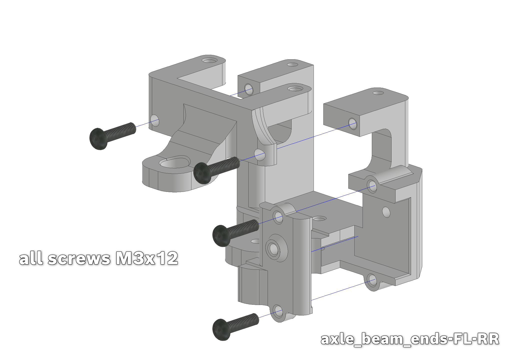
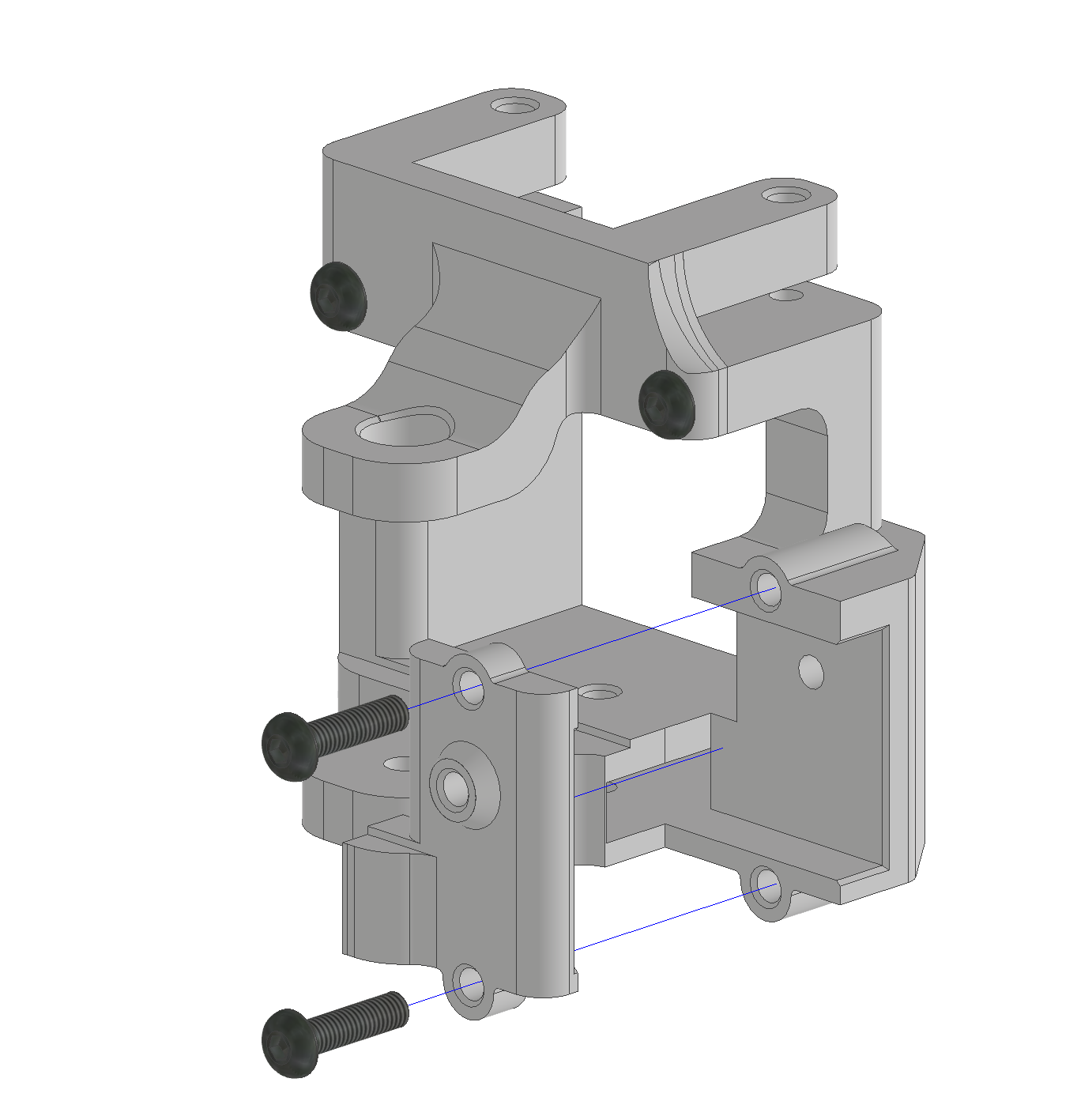
2x axle_beam-ends-FL-RR → for the front-left/rear-right
2x axle_beam-ends-FR-RL → for the front-right/rear-left
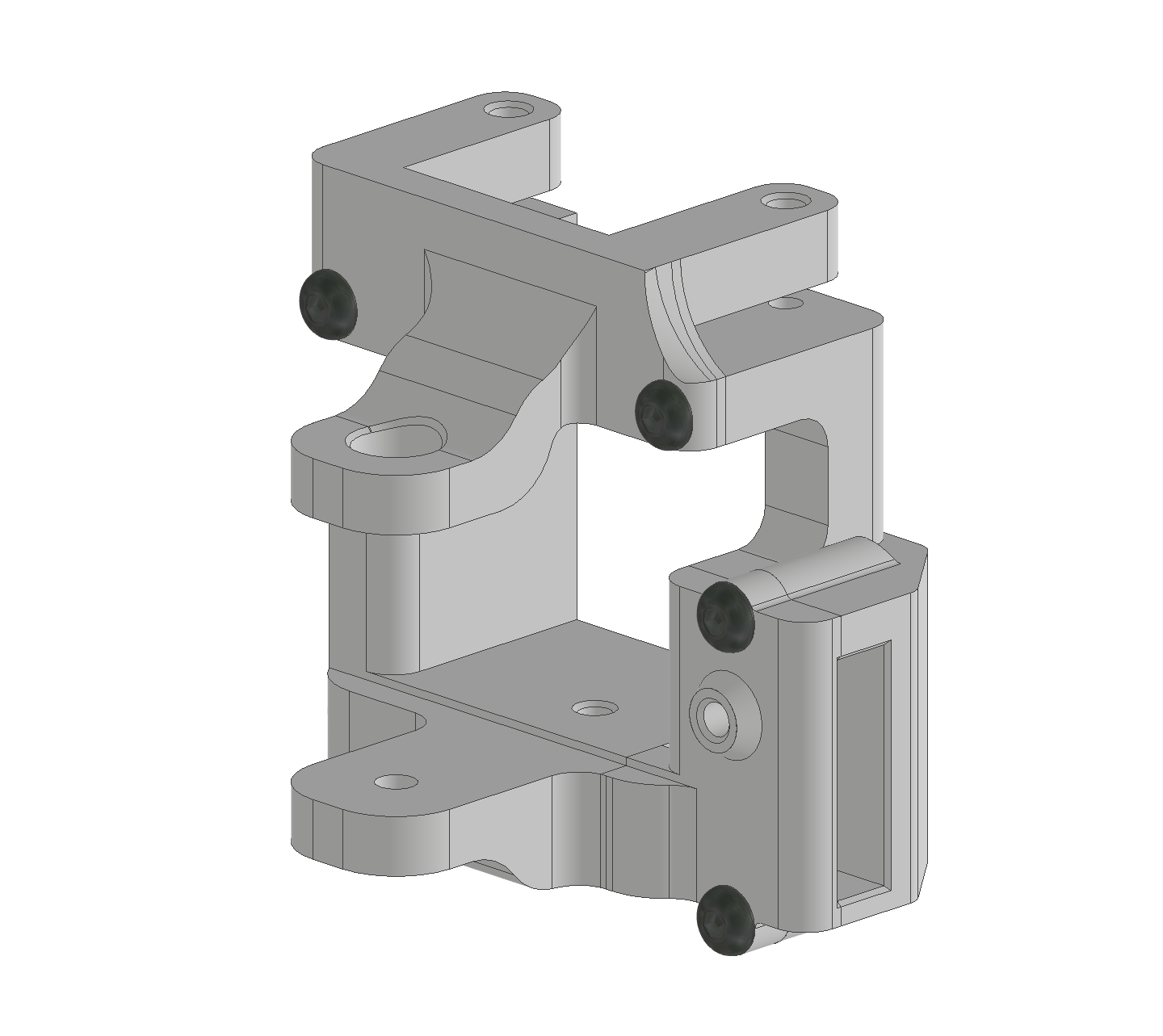
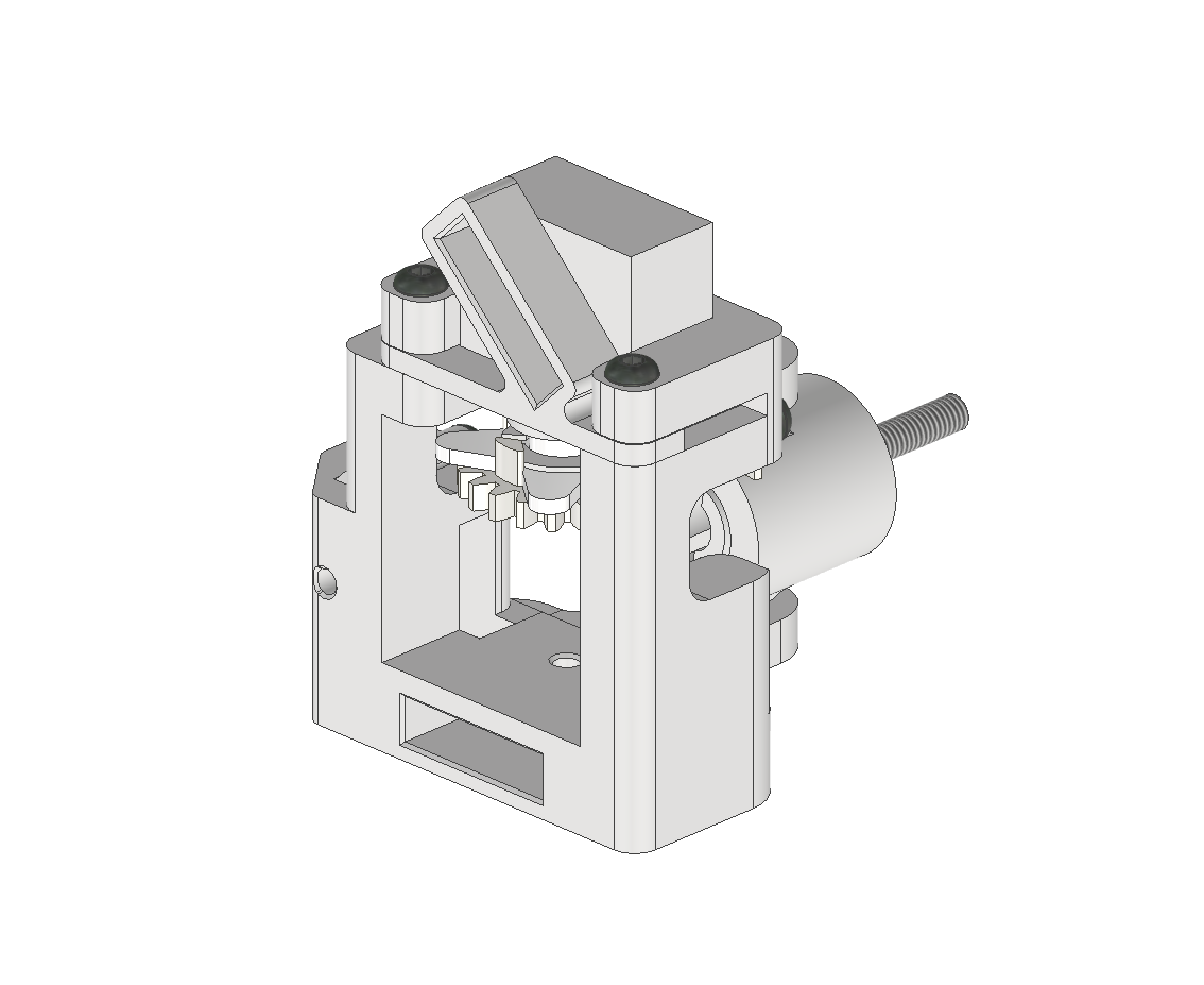
Simply fasten the the upper part and the clamp with M3x12-screws to the main body. Refer to the images (depicting axle_beam-ends-FL-RR) below. Make sure you don't mix up the parts for the FL-RR ("front left - rear right") and FR-RL - assemblies ("front right - rear left"). They differ in the sense that they are mirrored.
ESD Car 2.0 - Assembly of the axle_beam-ends(part).mp4
Assembly of the axle-beam_ends (assembly)
Now we can start with the actual axle_beam-ends-assembly.
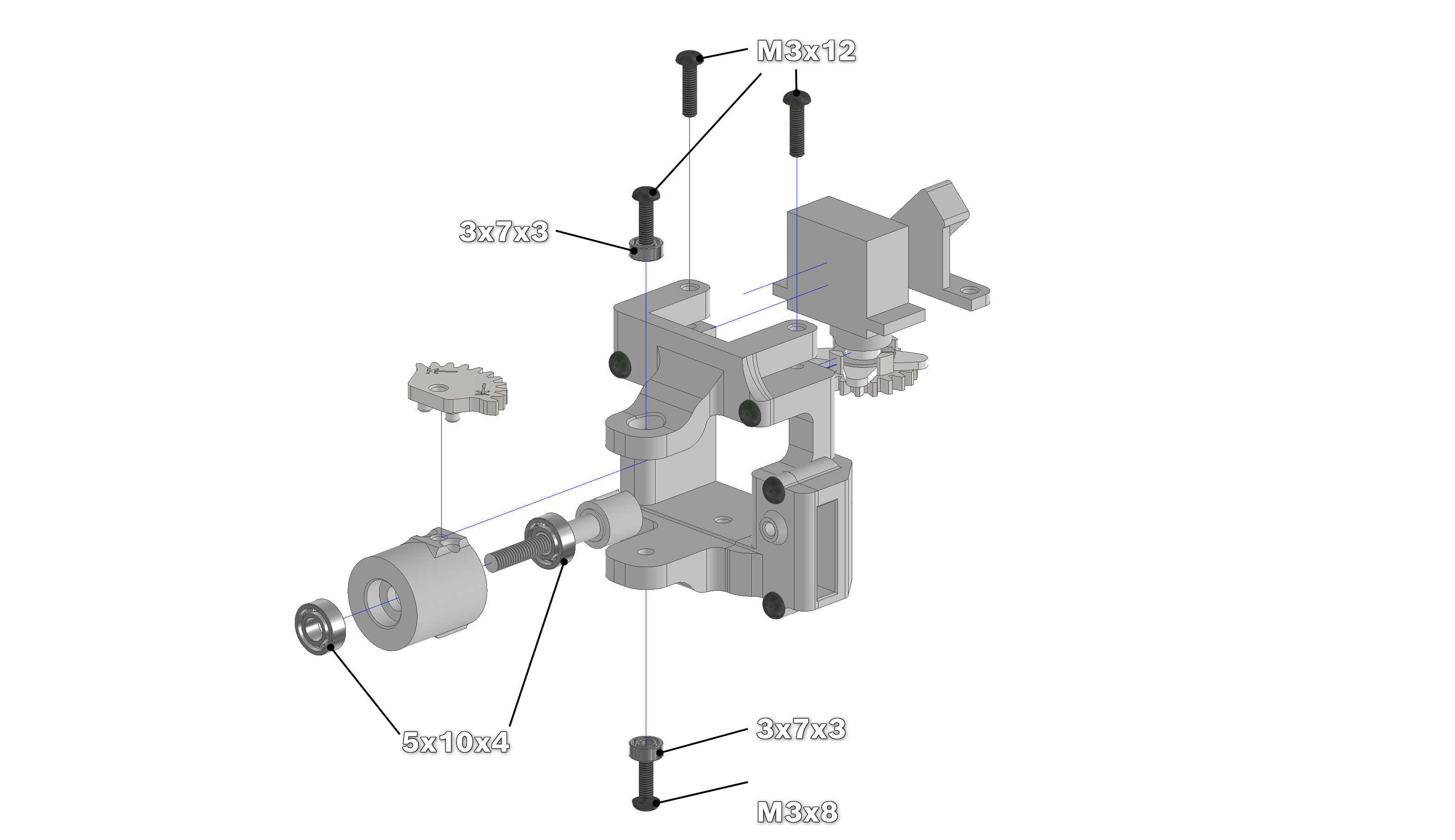
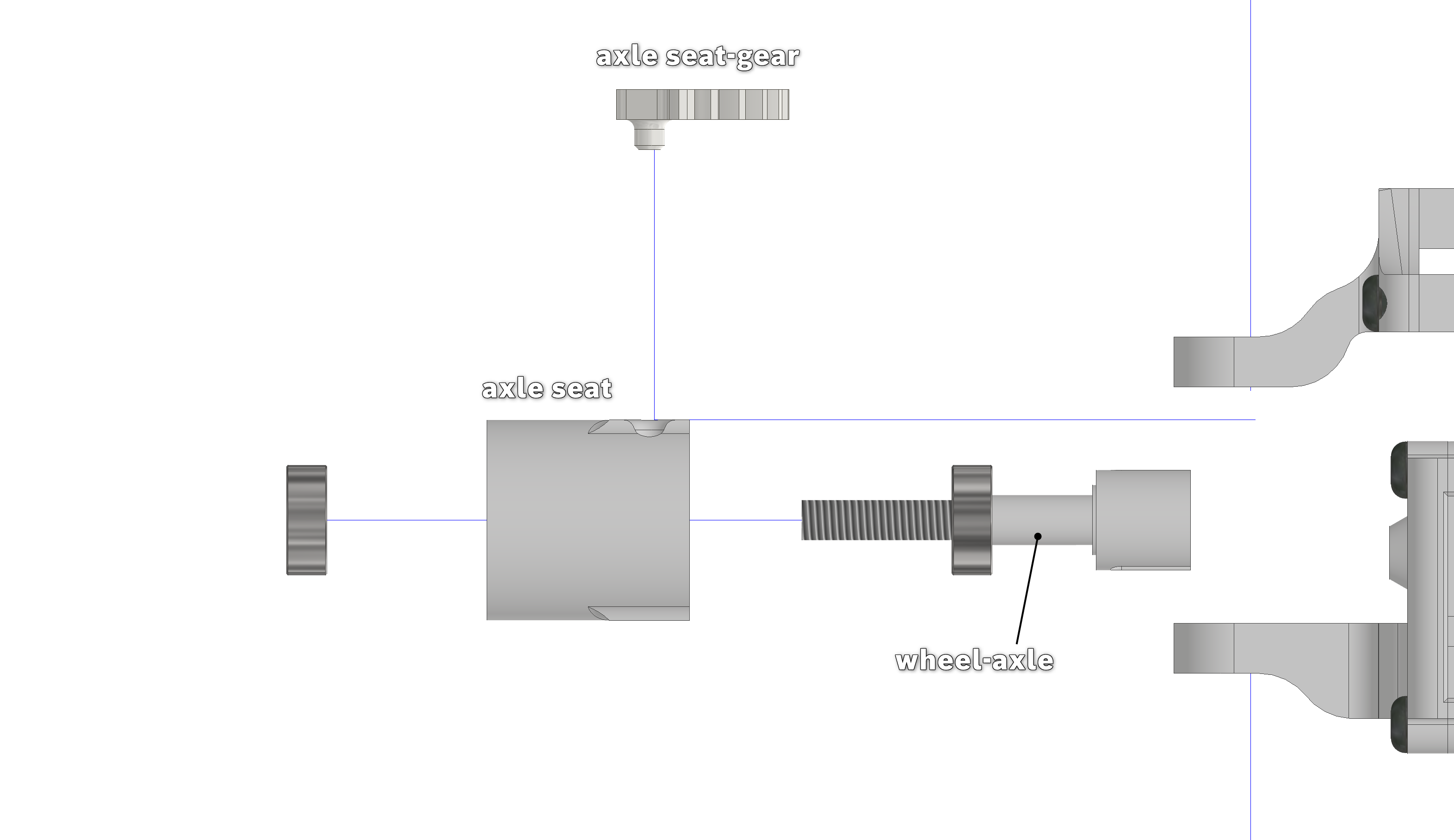
For this, take the axle_seat and make sure the inside of both sides are clear of any debris. Press two 5x10x4-bearings into both sides. For the bearing sitting deep inside the axle-seat you can use the printed 10mm-7mm_bearing_press. Be careful as to not press the bearings in at an angle. If the wheel_axle can spin in the axle_seat without any meaningful resistance (the bearings themself have a bit of drag), then you have installed the parts correctly.
Into each of the two arms of the main-part of the assembly, push a 3x7x3-bearing into. Do this by either using a vice or sticking a screw, with a nut on the other, end through it and tightening it. Make sure that the bearing is inserted straight. Once again, be even more careful this time that the bearing-seats are clean and smooth! Otherwise, the arms could split.
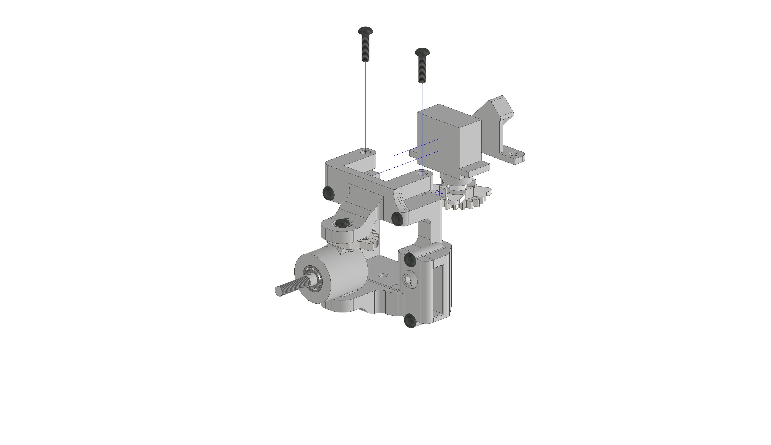
Take the (partial) axle_seat-gearEncoded and push it into the two slots on top of the axle_seat. Then take the assembled axle-seat, line its holes up with the main-body's arms and secure it with a M3x12-screw on top and a M3x8-screw at the bottom. Make sure, that with the screws tightened, the axle_seat can spin left and right without any meaningful resistance. There should also be a small gap (~0,5mm) between the axle_seat/gear and the arms.
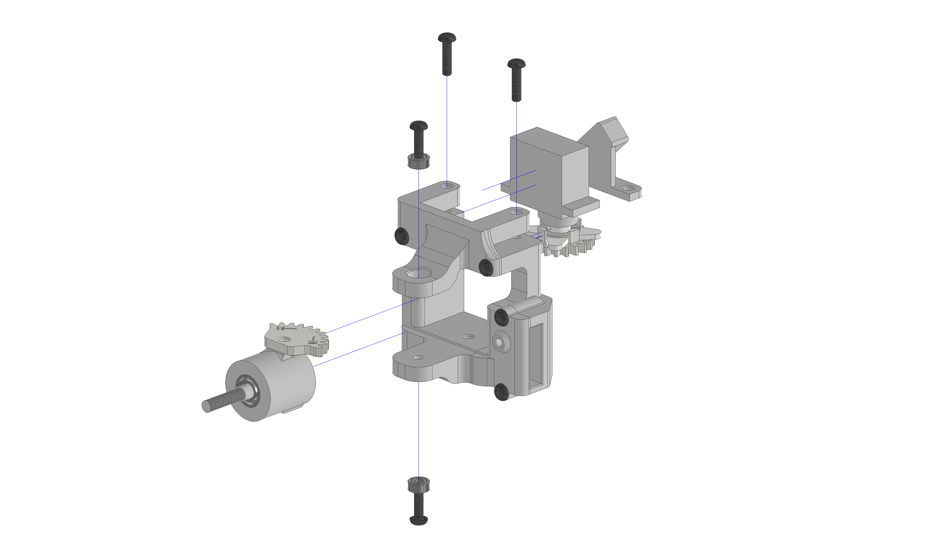
Take the servo-horn (cross with four arms of equal length) and push the servo-gear onto it. Then take the lock-ring (thin printed ring with a gap) and push it into the slots of the pillars of the gear. You can use a screw-driver for this. Now you can push the servo-horn onto the servo and screw it tight with the provided screw.
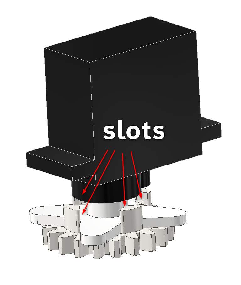
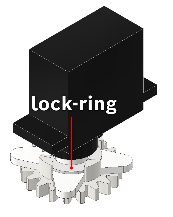
Now push the assembled servo upside down into the slot on top of the main-body. The orientation of the servo matters. Its gear should be in line with the axle_seat gear. Make sure that the wheel-axle sticks somewhat straight away from the remaining assembly before you mesh the servo-gear with the axle_seat gear. You will calibrate the neutral position at a later point with the help of a calibration software (see ESD Car 2.0 - Software Documentation).
Lastly, push the latchet into the slot as well and keep it in place with two M3x12-screws.
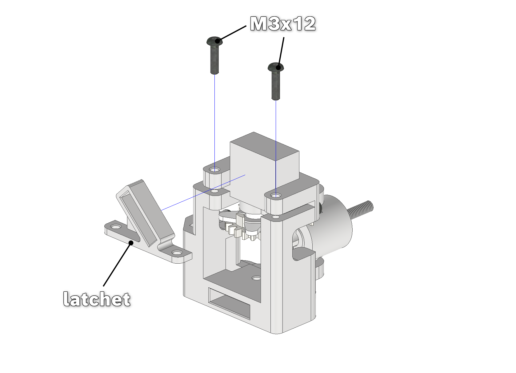
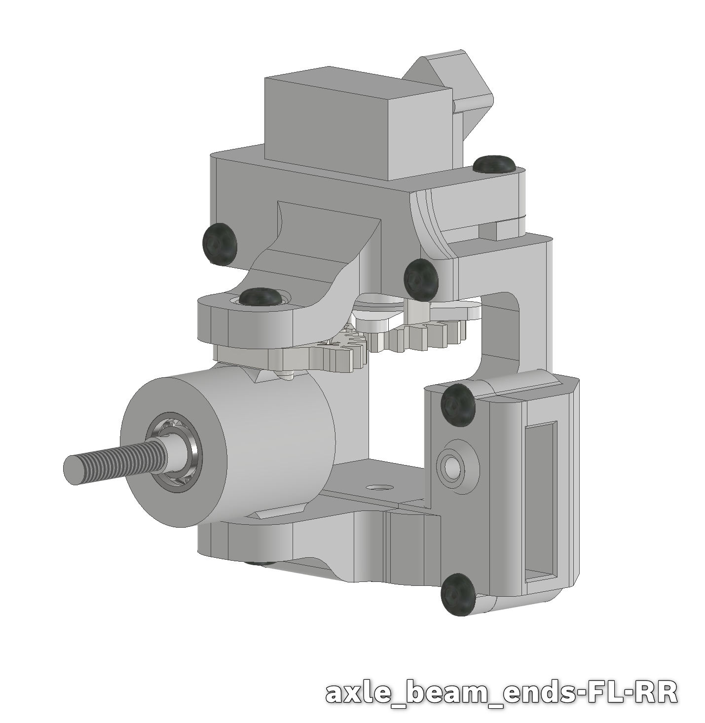
Repeat this for the other side as well (axle_beam_ends-FR-RL). The other two assemblies will be used for the wheel-encoder.
Keep in mind that there are two different main-bodies:
assemble 1x axle_beam_ends-FL-RR → for the front-left/rear-right
assemble 1x axle_beam_ends-FR-RL → for the front-right/rear-left
ESD Car 2.0 - Assembly of the axle_beam-ends (assembly).mp4
Encoder
There exist different iterations of the encoded axle-seat (axle_seatEncoded), changing the distance between the encoder and its code-wheel (diameter of operation), in case your printer has trouble printing accurately. Follow these instructions using the version "220" (22,0mm). After assembling the vehicle you will have to test the signal-quality (in ESD Car 2.0 - Software Documentation), swapping the axle-seat out for a different size, if needed.
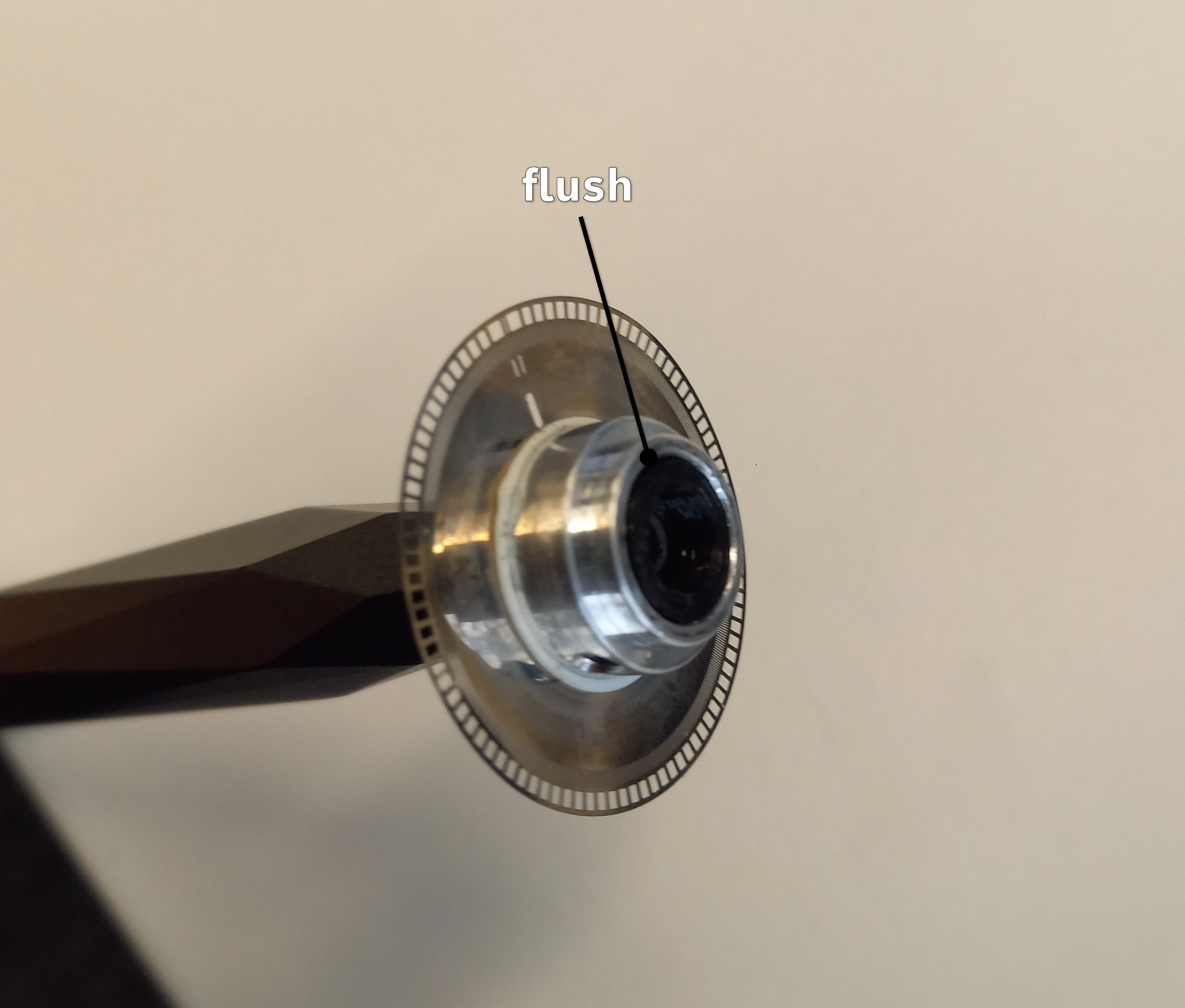
To house the wheel-encoder, push one 5x10x4-bearing into the backside of the axle_seatEncoded (main body). Push the sensor itself fully into its slot. The face of the sensor-slit must either be flush with or sightly inside the axle-seat (see the images below).
Push the ec_codeWheel_Axis (small bushing) into the code-wheel until it sits flush. This can be easily done by placing the bushing on a table and pushing the code-wheel onto it. Be careful to only push on the hub of the code-wheel as to not bend it.
Place the rim of the code-wheel in the sensor and over the axle_seatEncoded, then push the wheel-axle through those parts. To fully seat the wheel-axle, stand the assembly on the it. Push the ec_codeWheel_Axis-Press over the wheel-axle and push on it/hit it until the wheel-axle is fully seated. Then remove the press. The pin-hole in the wheel-axle should now be fully visible or alternatively, a 2x10-pin (supplied with the wheel_drive) should fit inside the hole.
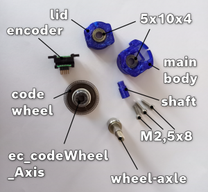
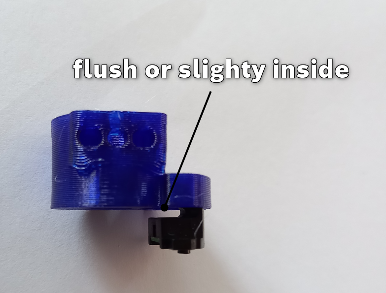
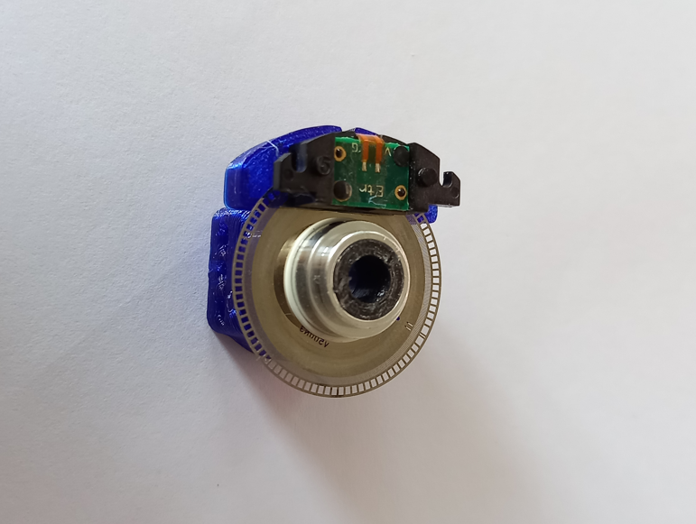
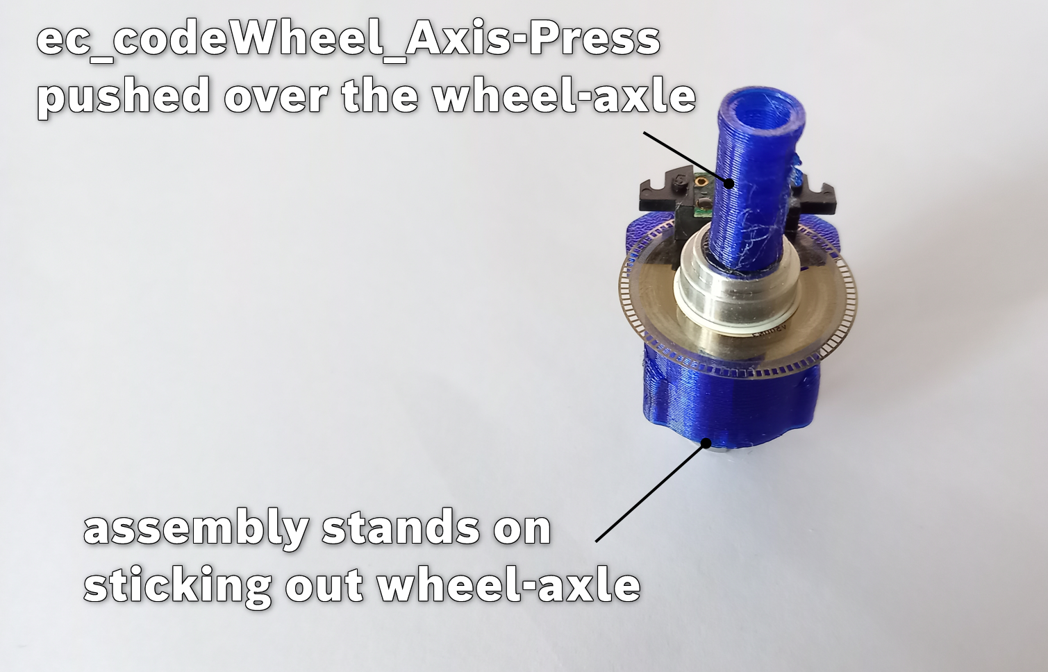
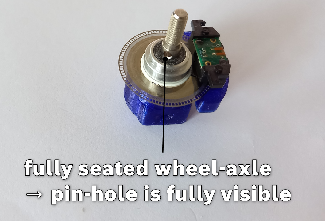
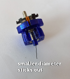
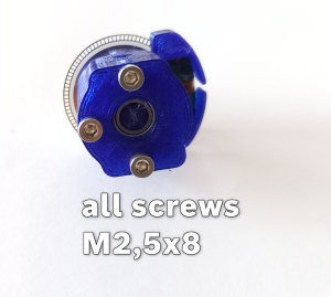
Push the shaft of the axle_seatEncoded into the backside of the wheel-axle, with the smaller diameter sticking out. Now push the bearing into the lid of the axle_seatEncoded. Push the bearing and thus the lid onto the shaft and screw the lid and main body together with 3 M2,5x8-screws.
Push the axle_seat-gearEncoded onto the axle-seat and install it in the axle_beam_ends-FL-RR the same way you did with the non-encoded versions, including the servo.
Note that you can install the wheels at nearly any point of this guide. Because of this, the images will depict the wheels at a later point. This also applies for different components.
Now only the wheels themselves are missing. Prepare four of them by pushing the rubber-tyres onto the printed rims, making sure they are not bumpy.
Then stick a 2x10-pin, which comes with the wheel-drive, through the hole of the wheel-axle and push the wheel-drive onto the axle so it locks the pin place. Stick the wheel on as well and fasten it with a M4-nut.
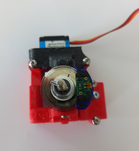
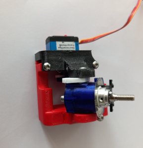
Repeat this assembly for the other side as well (axle_beam_ends-FR-RL).
Assembly of the gearbox
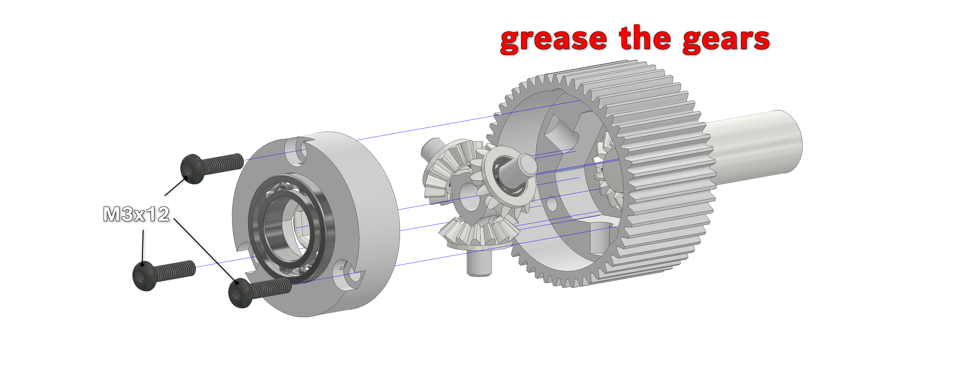
Take the small bevel gears and make sure the bearing-seats are clear of any loose filament strands. You can remove any debris with a small screwdriver and/or a wire-cutter. Press the bearings (5x8x2,5) into the gears by either laying them on a table and pushing the gear onto it or by pressing them together in a vice.
Take the inner cross (cross_throughhole) and make sure its three arms are somewhat smooth and round. If not, use some sandpaper or a sharp pair of engineers-pliers and twist the arms between the prongs. Push the gears onto the arms as far as they will go. It is okay if it takes some force.
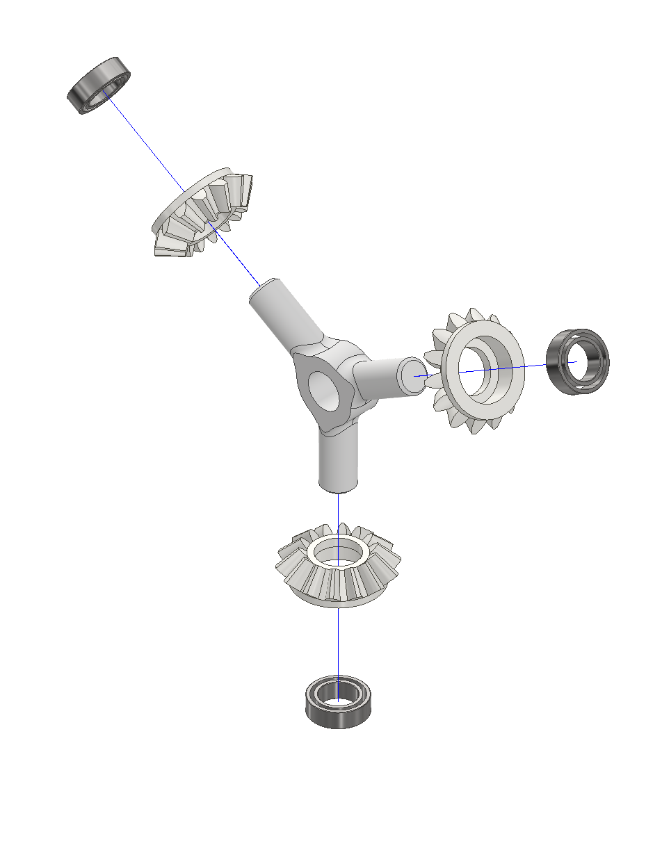
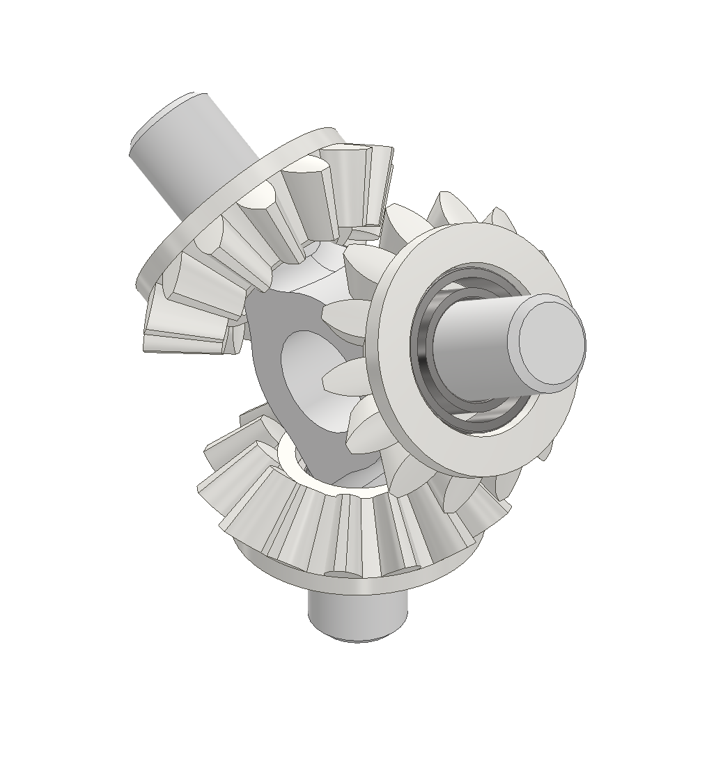
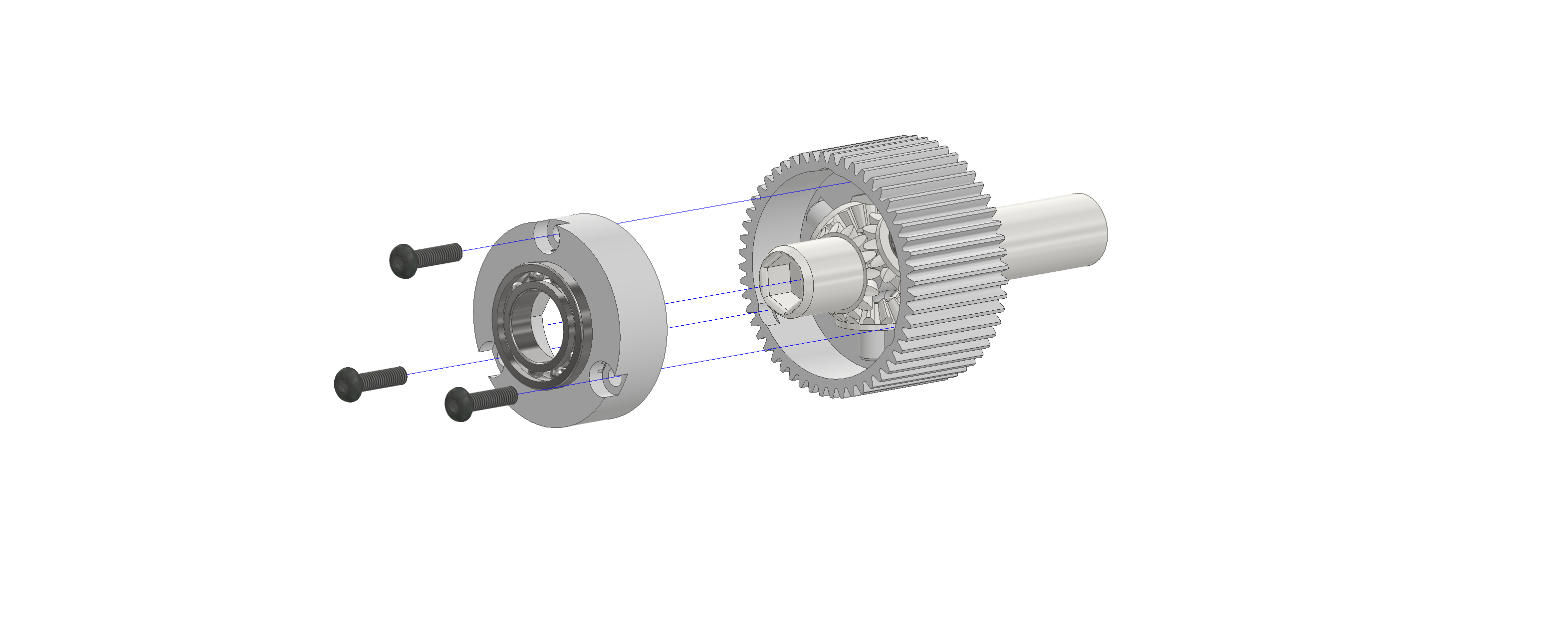
Take the long-shafted bevel-gear, push it into the bearing (12x21x5) and push them both into the "closed" side of the gearbox-housing (housing_bevelgearbox-outerRing). Make sure the bearing-seat is clear of any loose filament-strands. The bearing should stick ~2mm out.
Put the assembled inner cross inside the gearbox-housing and push the small bevel-gears outwards. Now put some grease onto the gears.
Push the short bevel-gear against the cross with its gears and twist it on the inner gears until they turn quite easily. The inner gears should now be close the inside-wall of the housing.
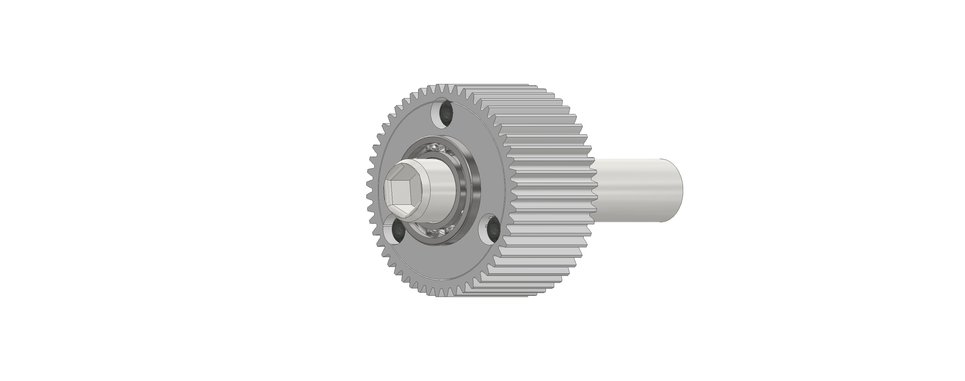
Push the bearing (12x21x5) inside the inner ring of the gearbox-housing (housing_bevelgearbox-innerRing), stick the short bevel-gear through it and push the assembled inner ring into the assembled housing.
Fasten them together with 3 M3X12-screws.
Assembly of the driven axle
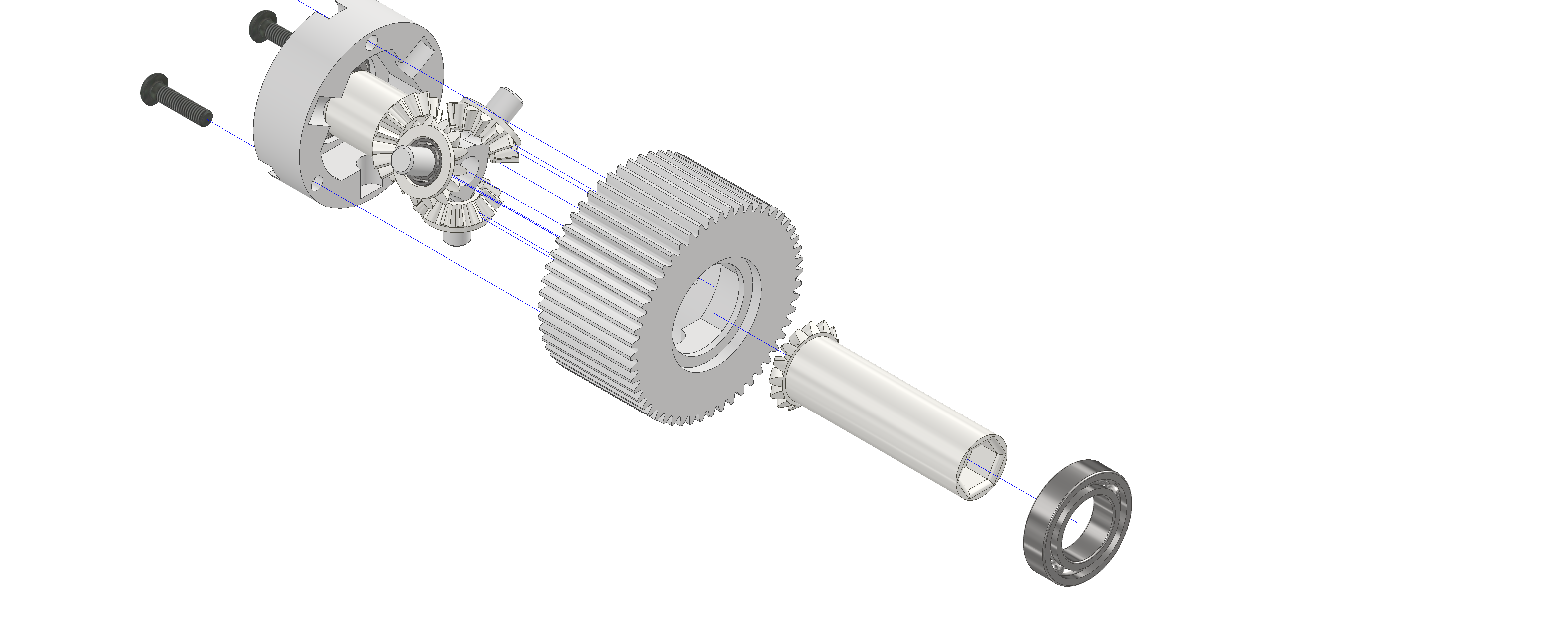
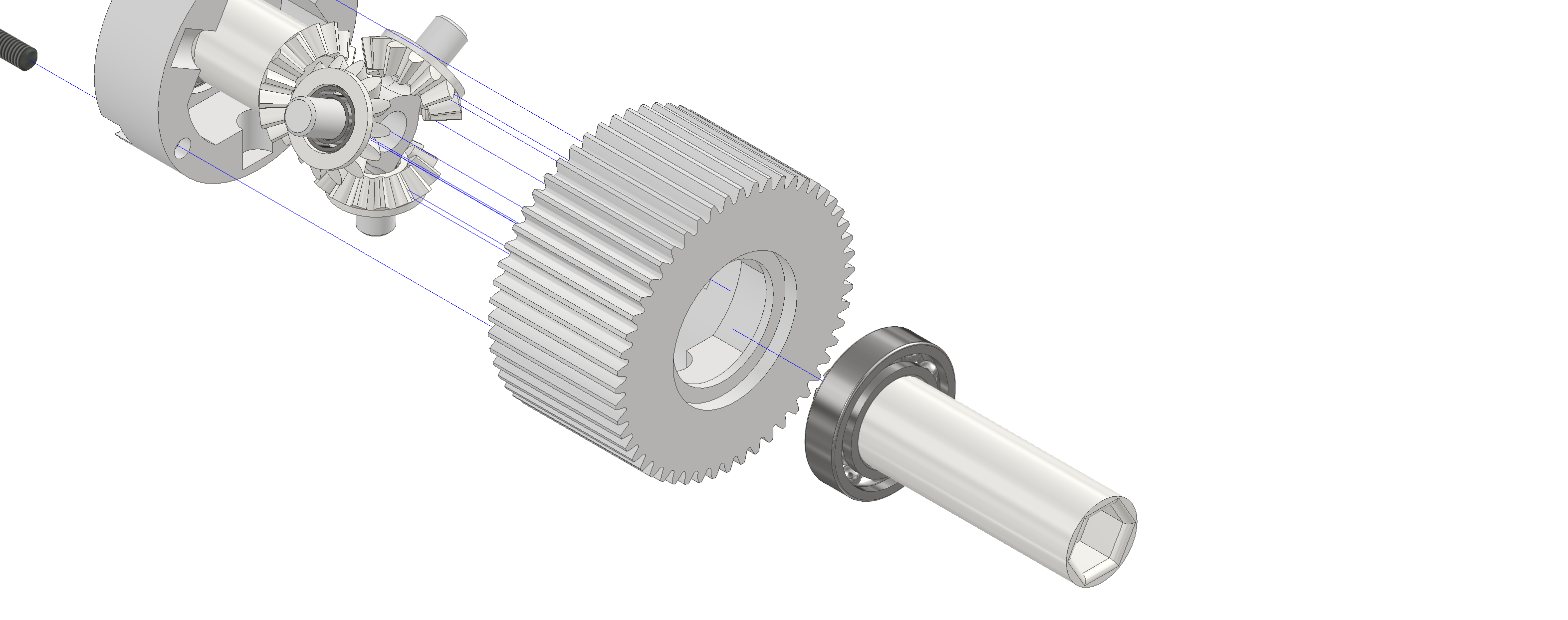
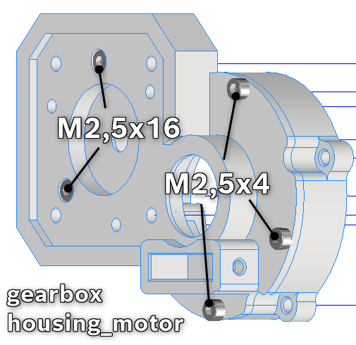
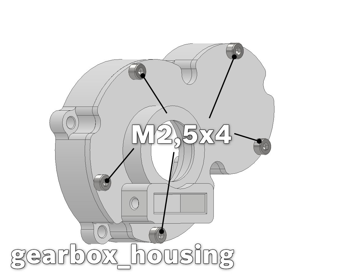
The two main bodies are the "gearbox_housing_motor-2mm" and the "gearbox_housing_fullyPrinted". Both consist of a main-ring/main-body and a lid. Before we can continue screw each lid with it's ring together using M2,5x4-screws, except for two holes (see in the image below where to use M2,5x16).
Push a big bearing (12x21x5) into the motor-housing.This is easiest done, by useing the 21mm_bearingPress. Lightly push the bearing in its seat in the gearbox_housing_motor, then place the bearing-press over it and clamp everything in a vice, pressing the bearing in.
Place the stepper motor into the square slot of the motor-housing with its shaft sticking through the small hole (not through the bearing). Fasten the motor with M3x12-screws, except for the countersunk hole by the bearing (M3x8). Push the previously assembled gearbox with the long shaft into the bearing. If the outputBevelGear_long or rather its bearing in the differential gearbox slips out, simply keep pushing everything into the housing, pressing the bearing back into the gearbox.
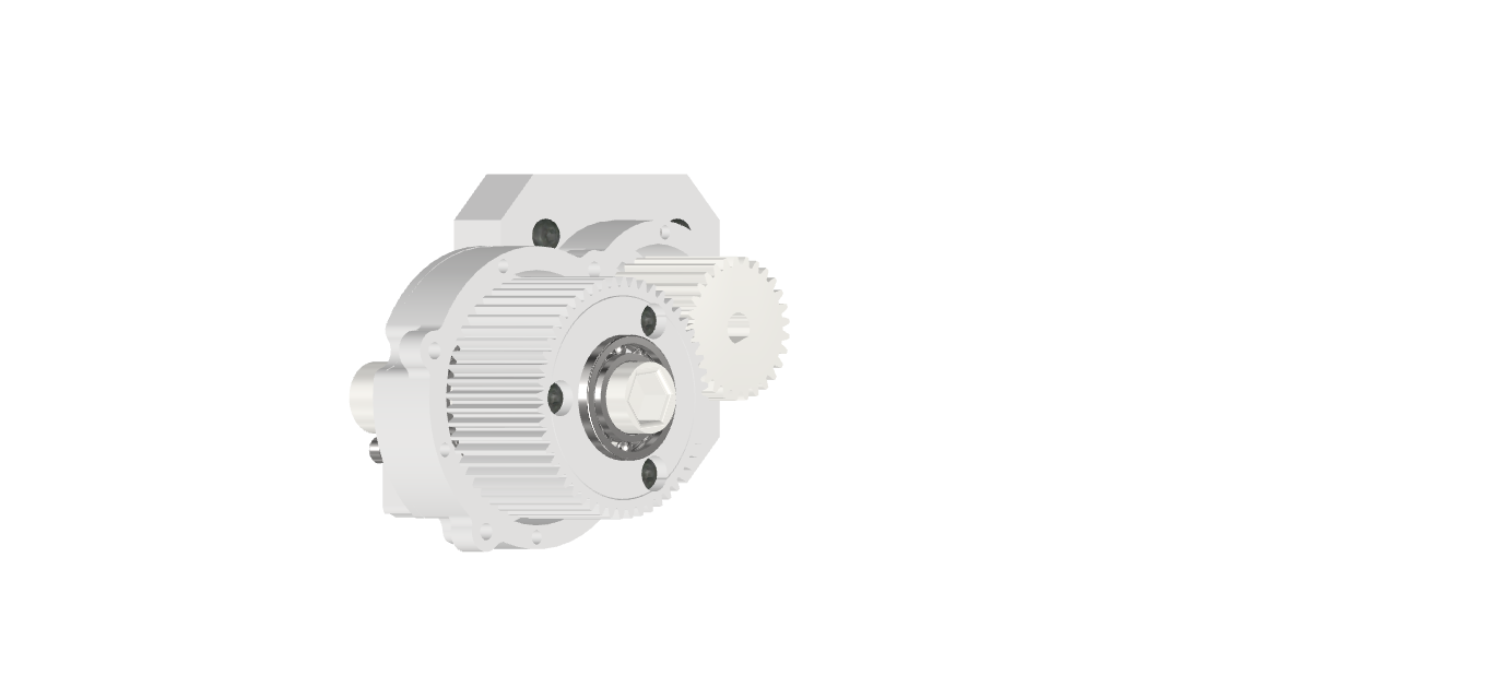
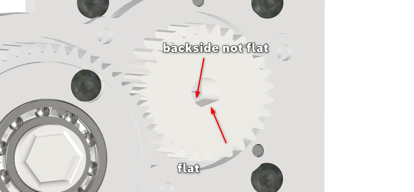
Then push the motor-gear onto the motor-shaft. Keep in mind, that the motor-gear must be orientated in such a way, that the round face of the inner hole is pushed onto the motor-shaft first. Make sure that the gear doesn't rub against the housing.
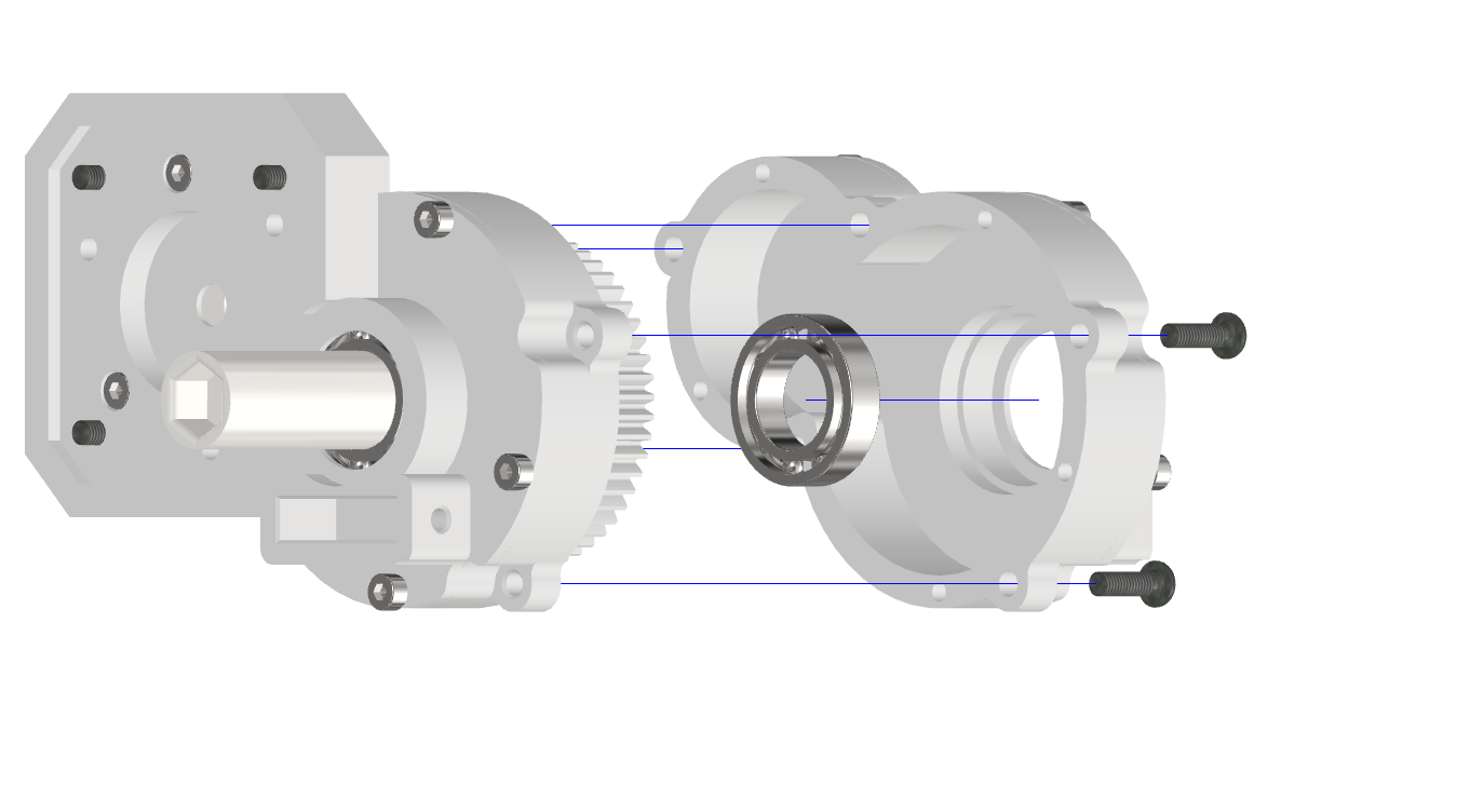
Press the bearing (12x21x5) into the other half of the housing ("gearbox_housing_fullyPrinted"), using the 21mm-bearing press.
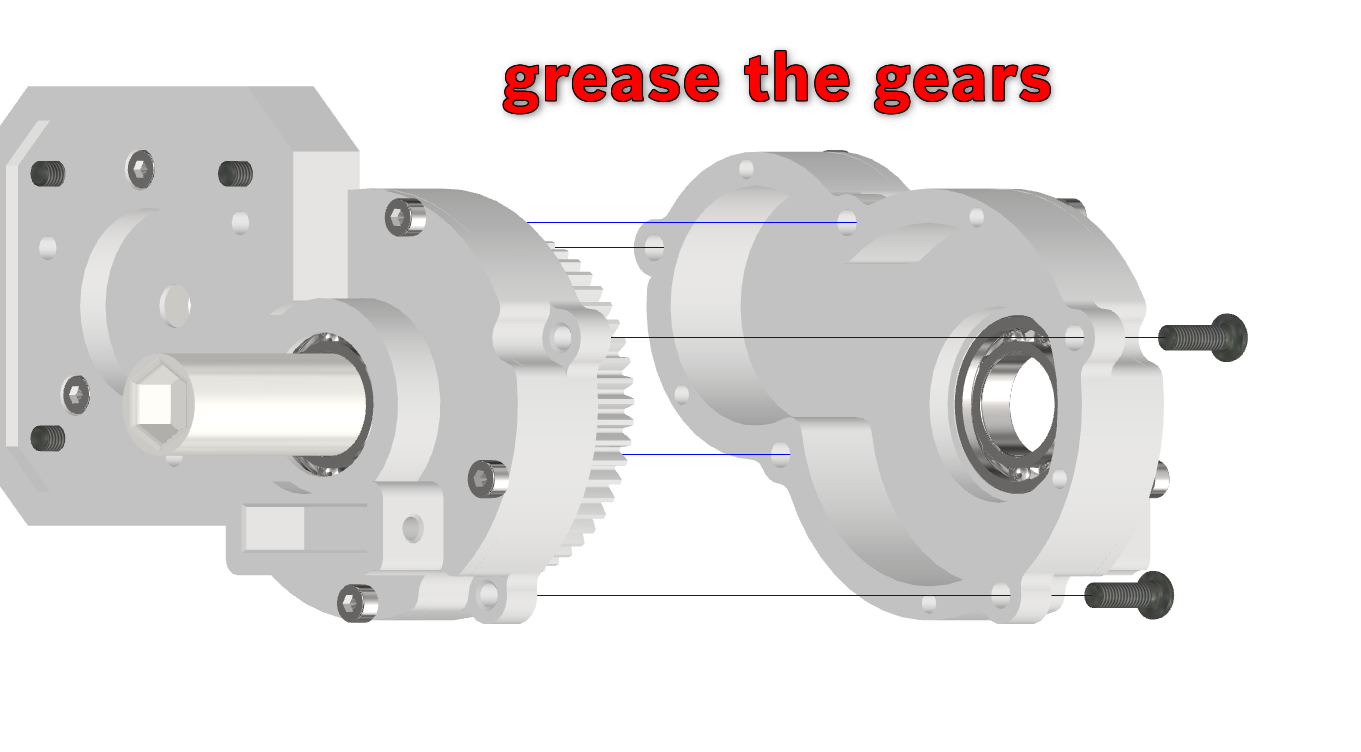
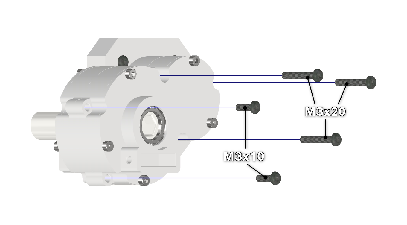
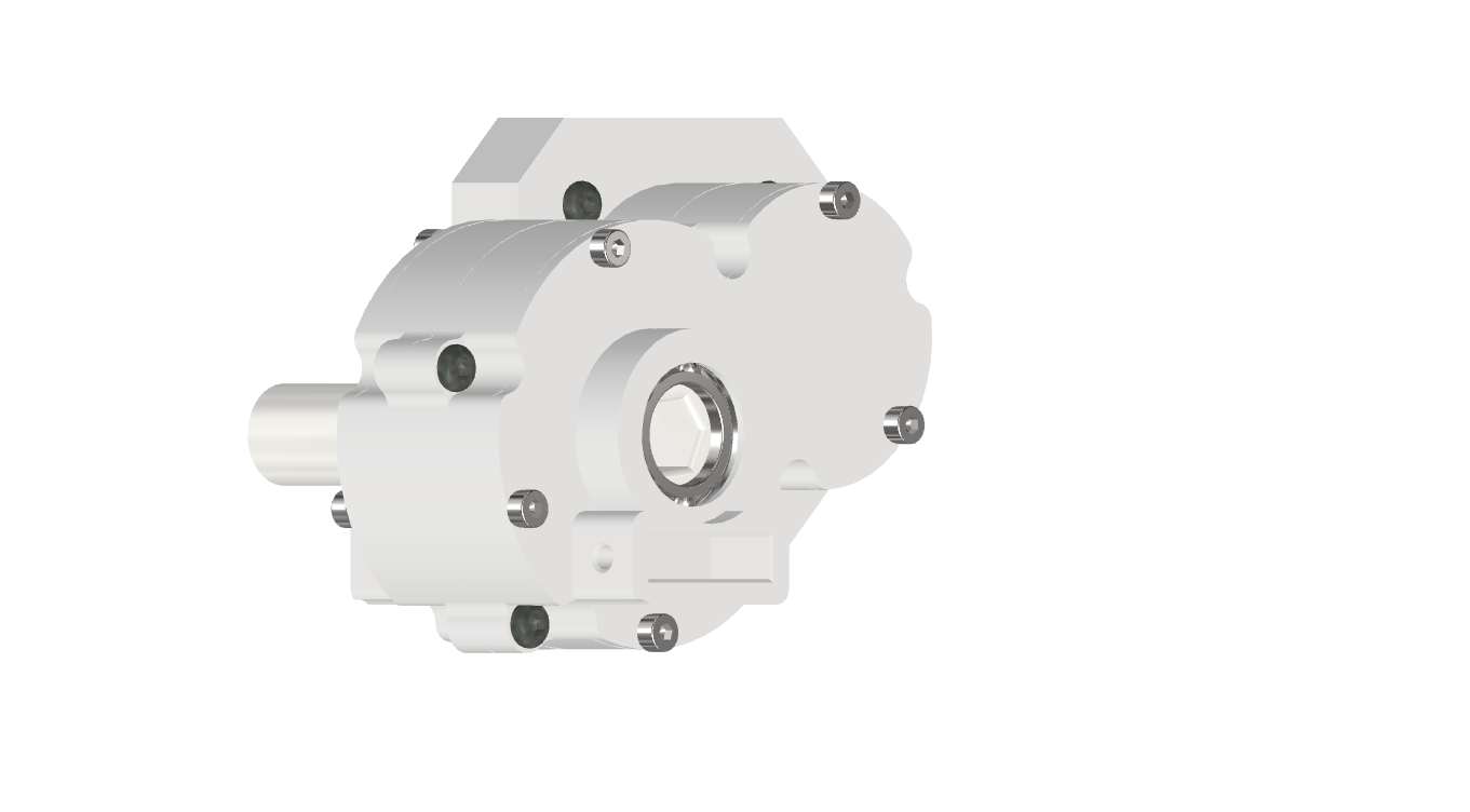
Put some grease on the gears and spread it a bit around by turning the gears, then fasten the two halves together, with the gearbox inside, using M3x10/M3x20-screws. Note that the M3x20-screws reach through the motor-ring into the motor-housing.
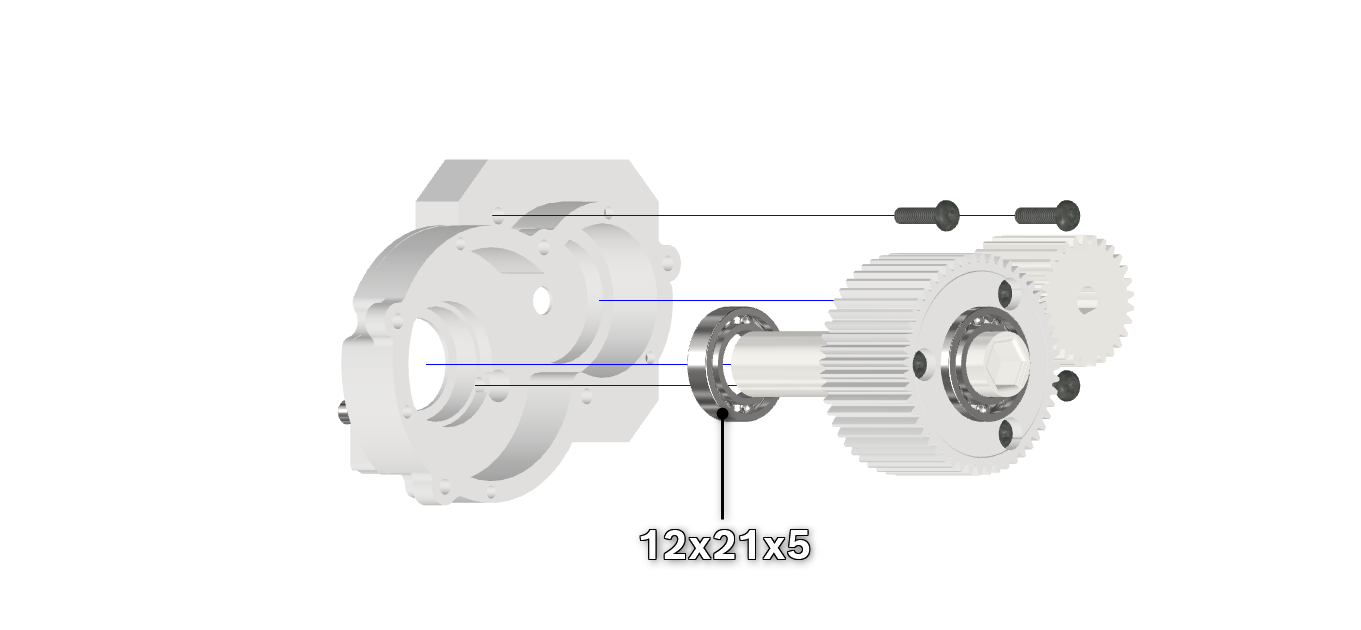
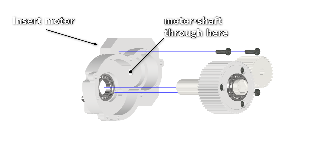
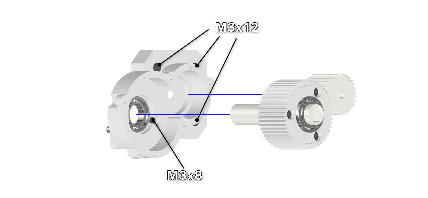
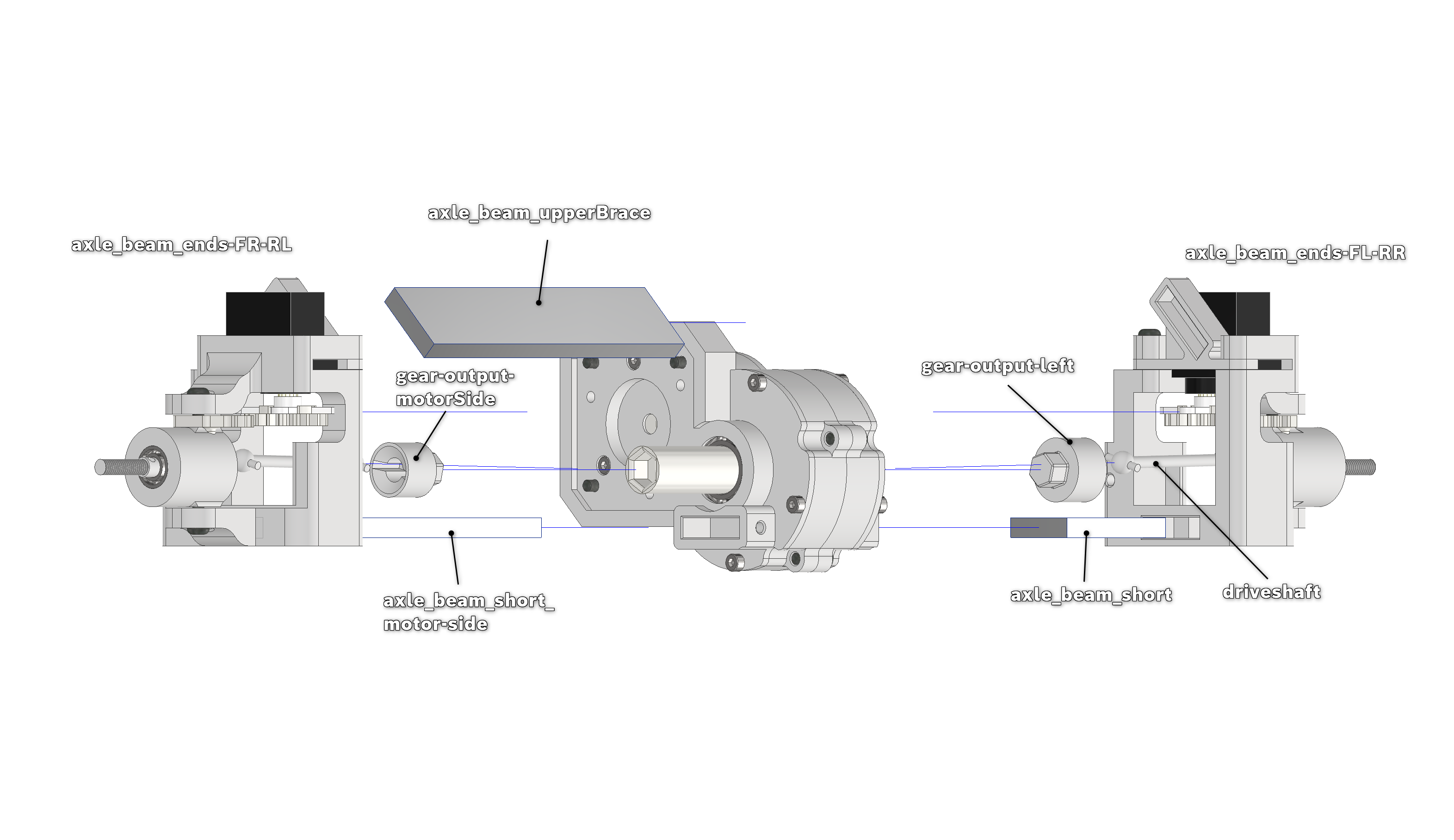
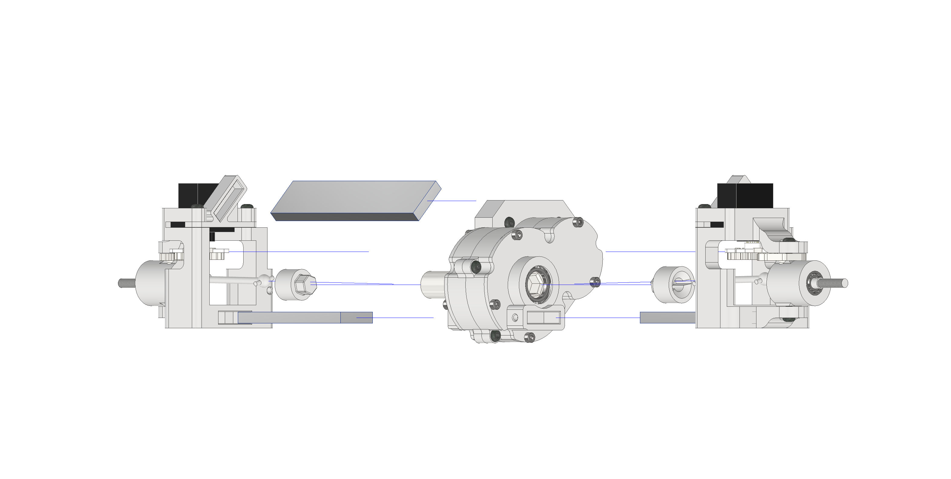
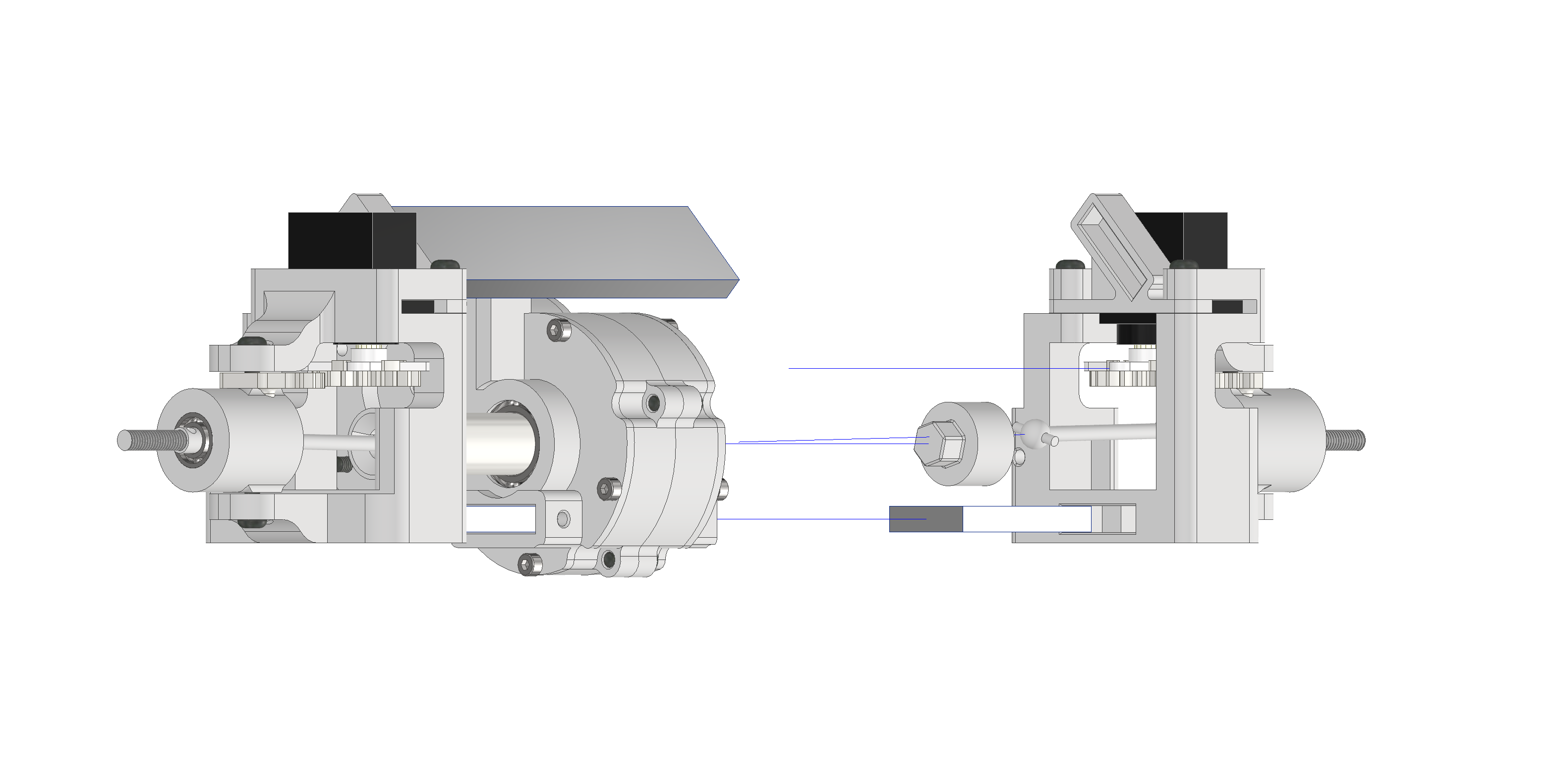
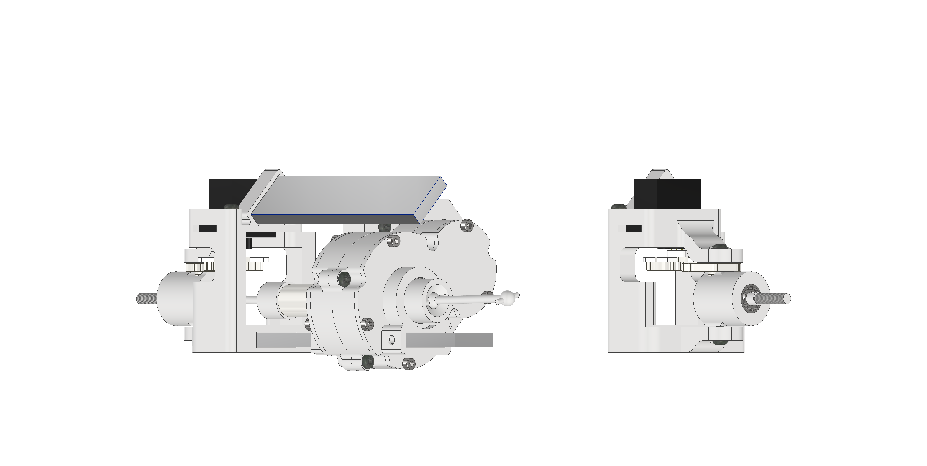
Take the longer of the axle-beams ("axle_beam_short_motor-side") and stick it into the gearbox-housing-half with the stepper-motor. If it doesn't stay inside the housing, you can fix it by clamping it with a M3x6-screw, screwed into the front of the housing.
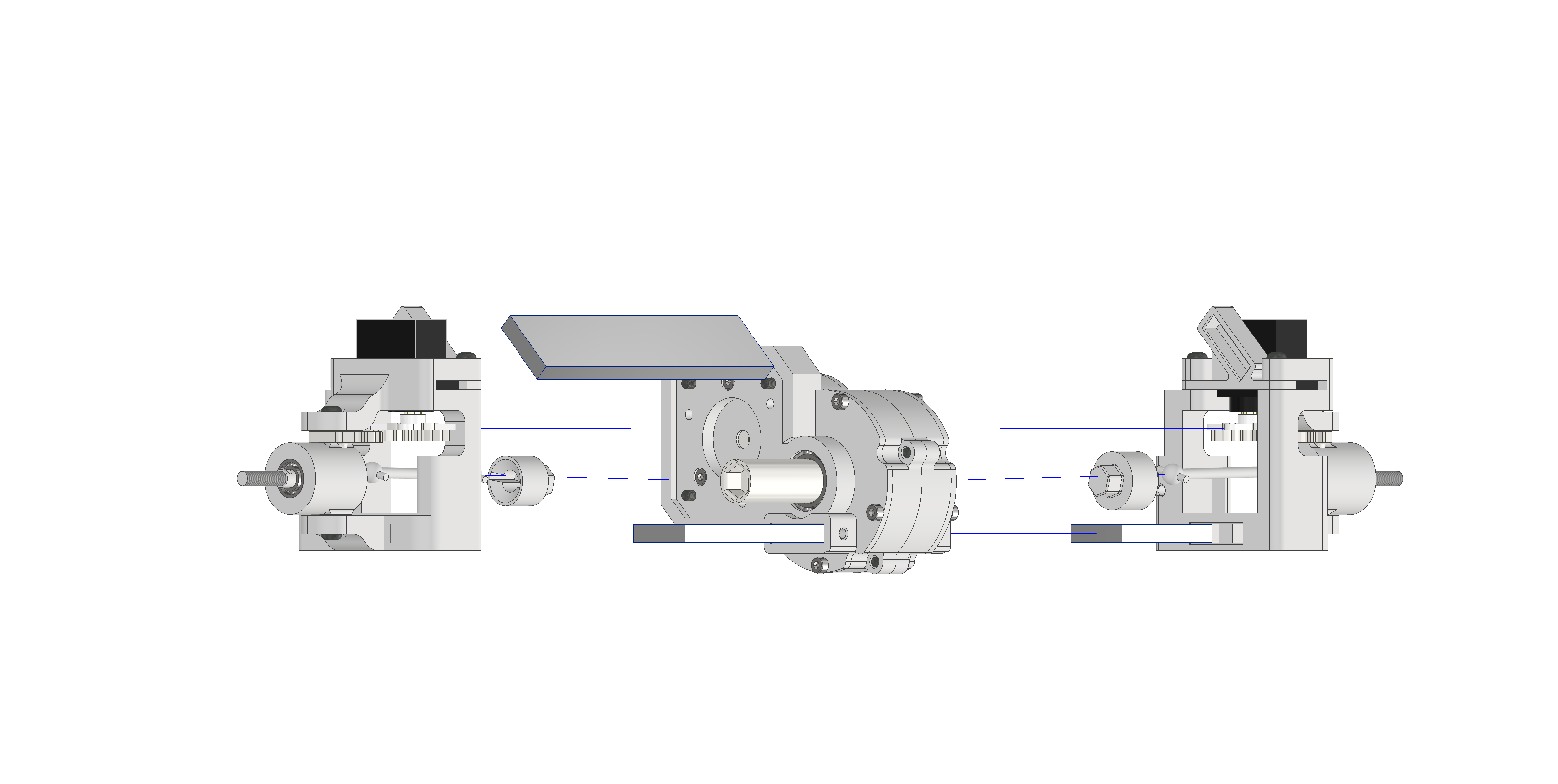
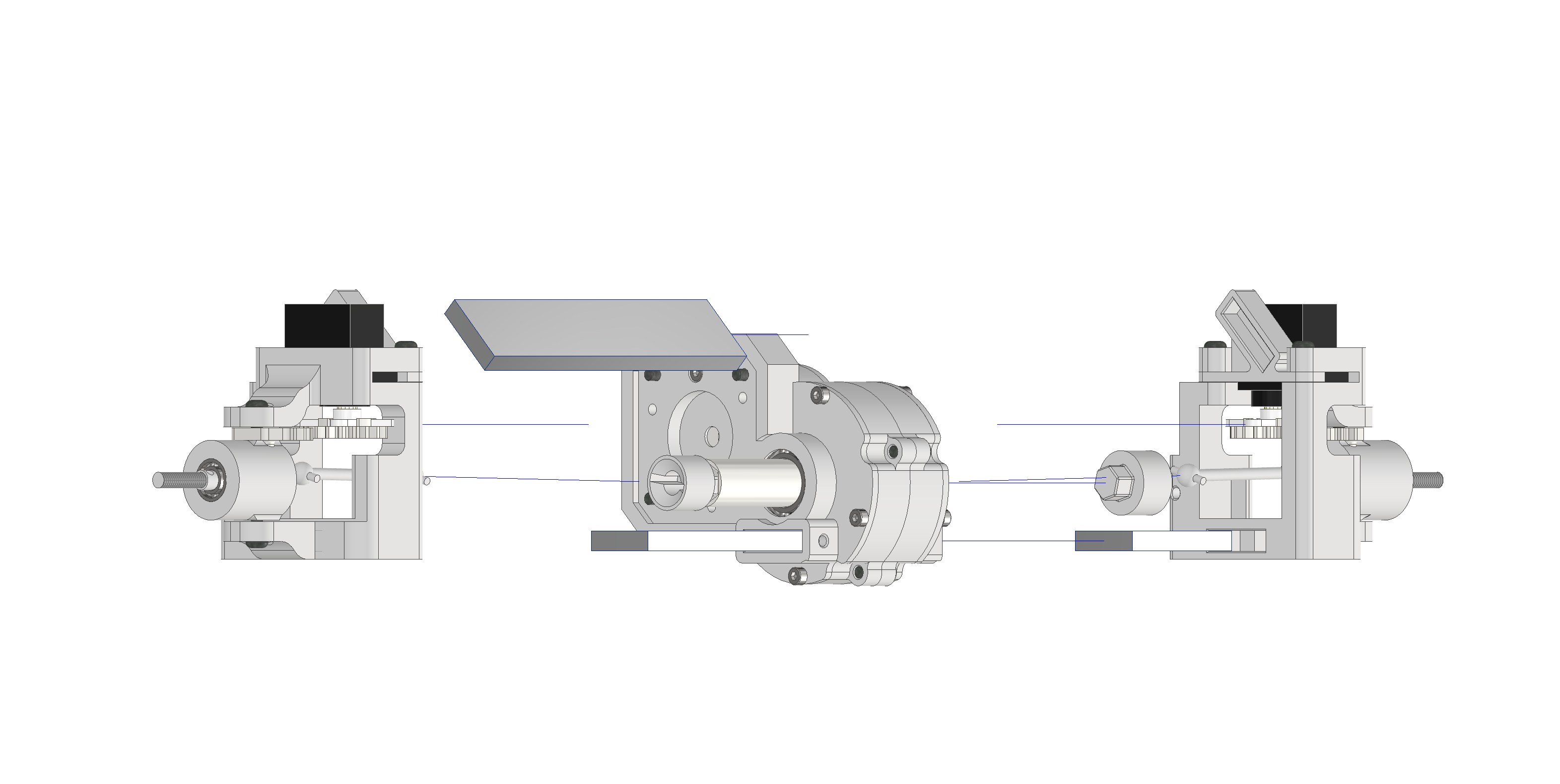
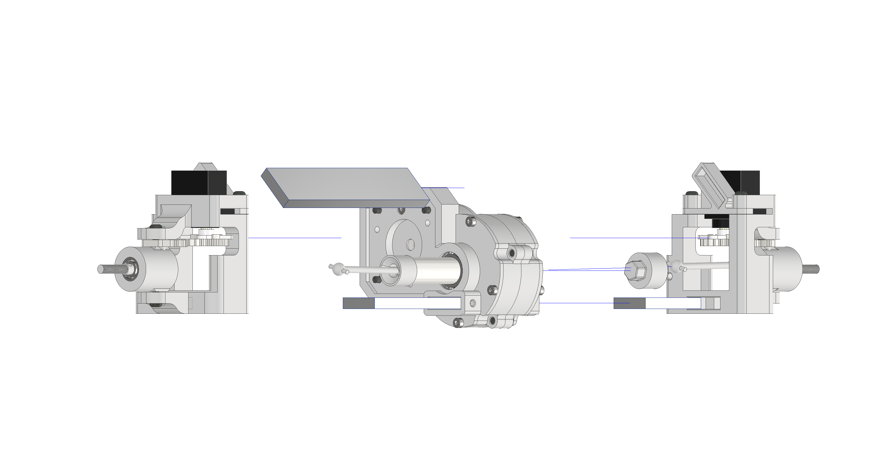
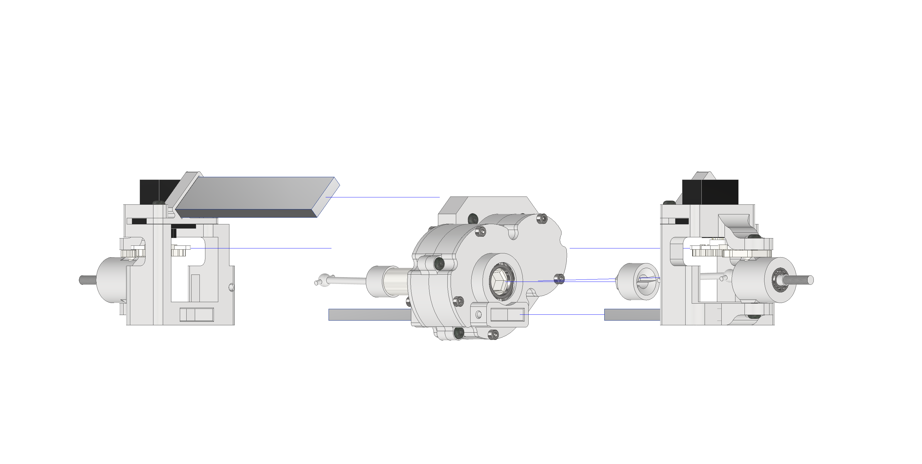
The next step is to push the thinner (smaller diameter) gear-output (gear_output-motorSide) into the long shaft of the gearbox, then push the driveshaft into the gear-output.
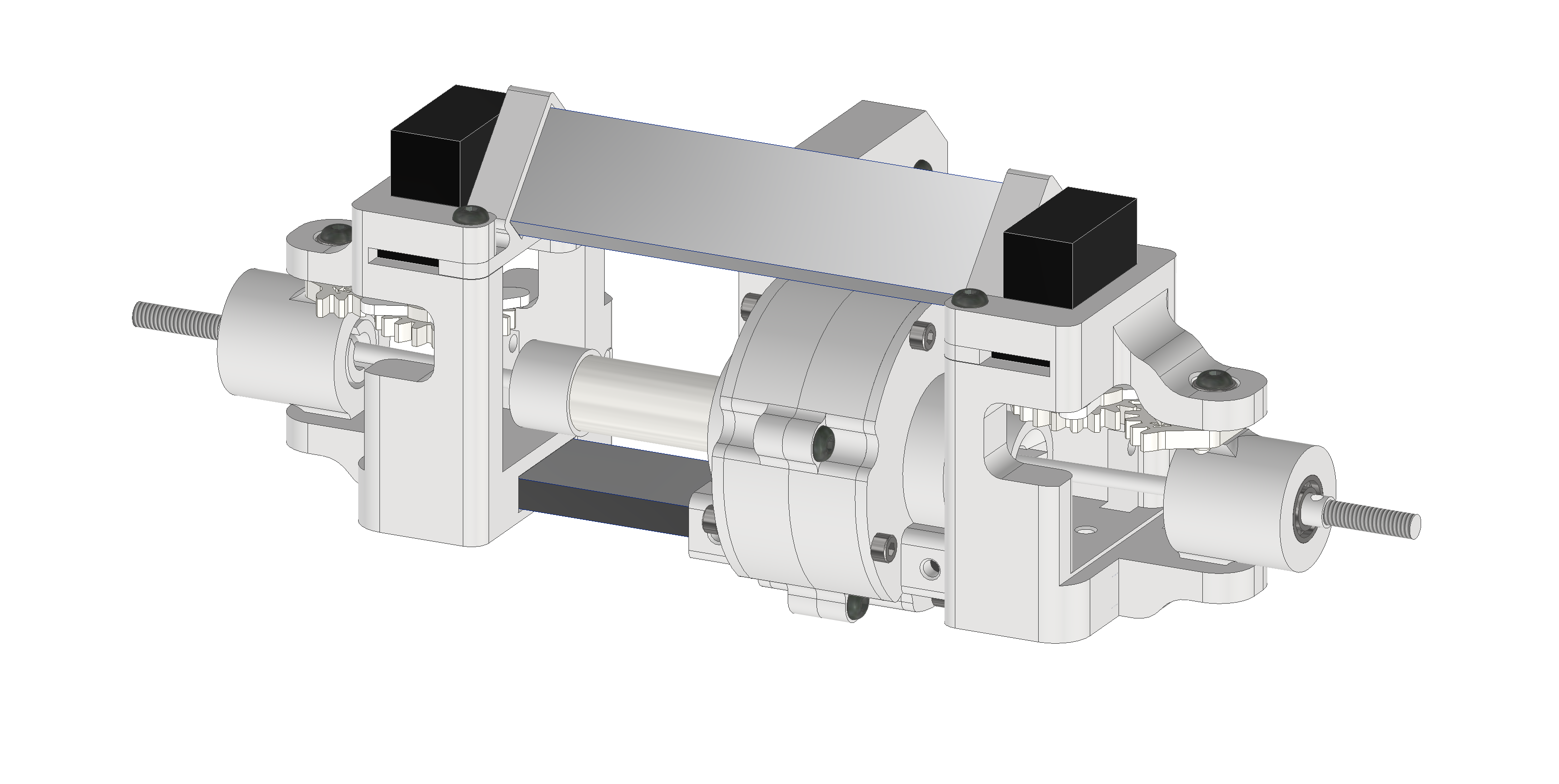
Hold the driveshaft horizontally and push the assembled axle_beam_ends-FR-RL onto the alu-beam, while also pushing the driveshaft into the wheel-axle. This can be quite tedious so make sure the slits on the wheel-axle are aligned with the pin of the driveshaft. Also moving and turning the wheel-axle and driveshaft around can help to fit everything together.
Now push the brace-beam (axle_beam_upperBrace) into the angled pocket of the latchet and repeat the previous steps for the other side, using the thicker gear-output (gear_output-left) and the assembled axle_beam_ends-FL-RR. If the beam-ends slip of the beams you can fix them in place via an M3x6-screw at the bottom of them.
With this, the driven axle and also the most complex assembly is finished!
Non-driven axle
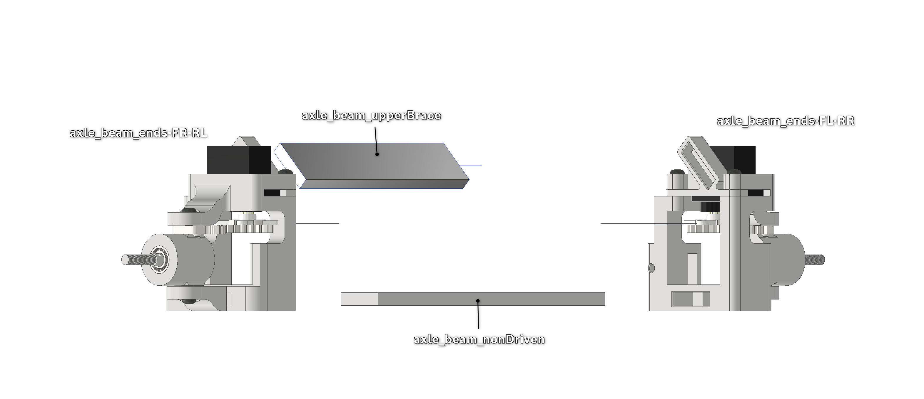
Simply push the axle_beam-upperBrace, axle_beam_nonDriven and the axle_beam-end assemblies together. If needed, you can lock the beam-ends in place with a M3x6-screw going into the bottom of each beam-end.
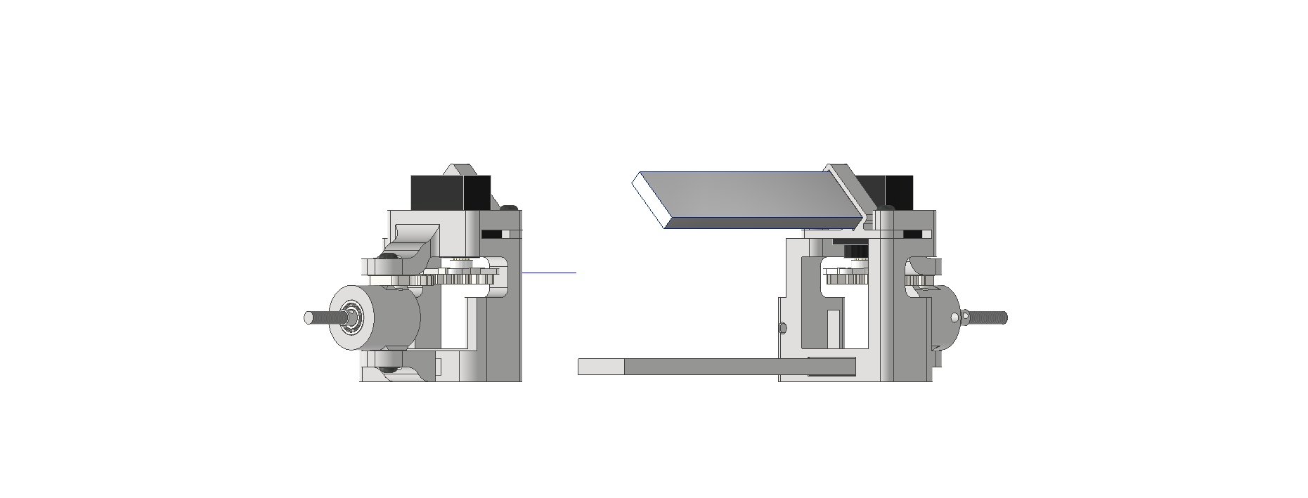
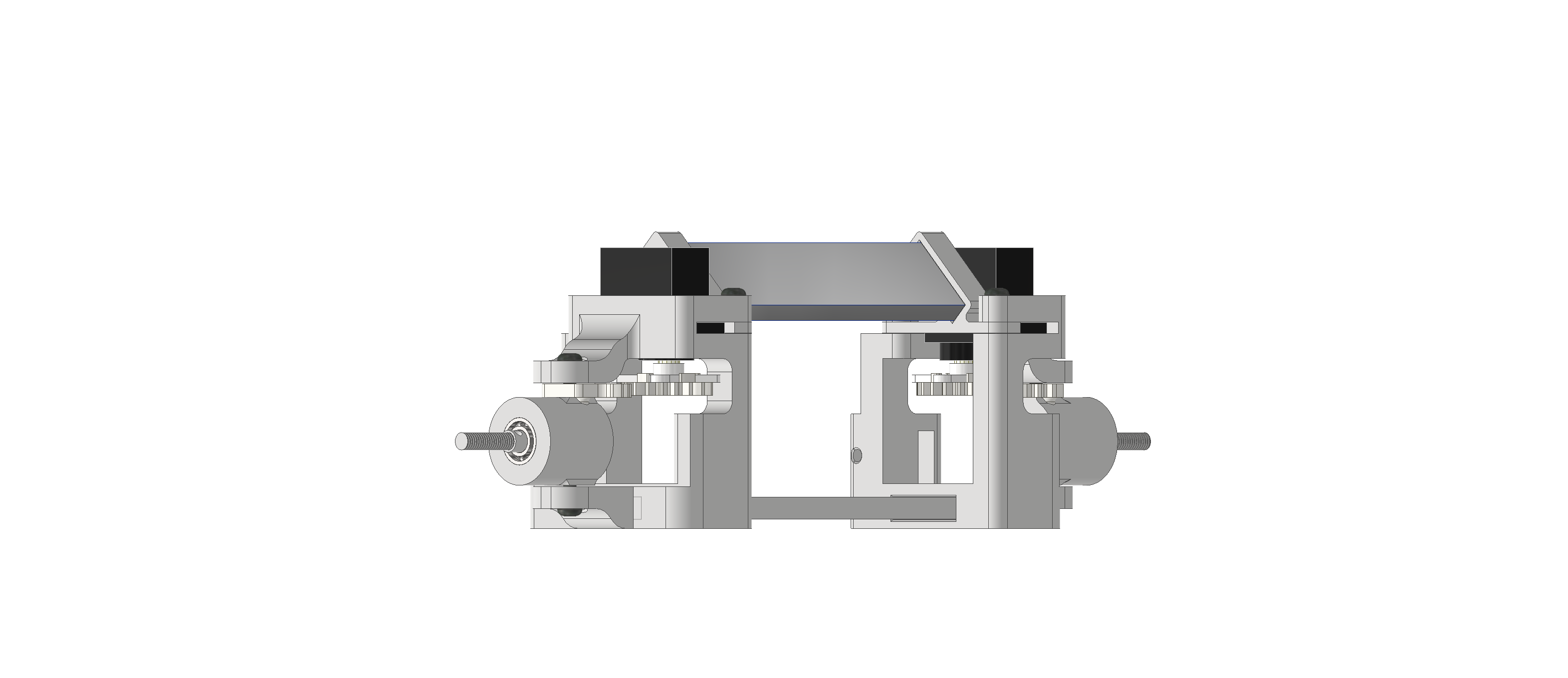
PCB-stack and mounting-plate
PCB-stack
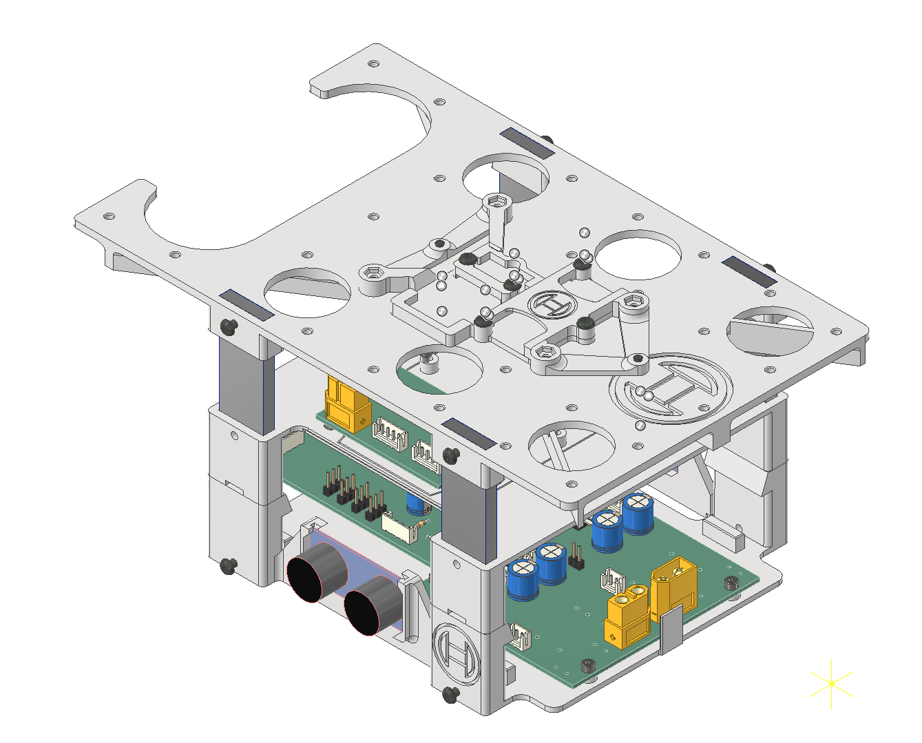
The PCB-mounts and the mounting plate form the "PCB-stack". This stack is one ipt-file, consisting of three different parts:
PCB_baseplate
PCB_topplate with the PCB_topInsert and Raspberry standoffs (standoff_Rasp)
mountingPlate and its sensors
PCB_baseplate
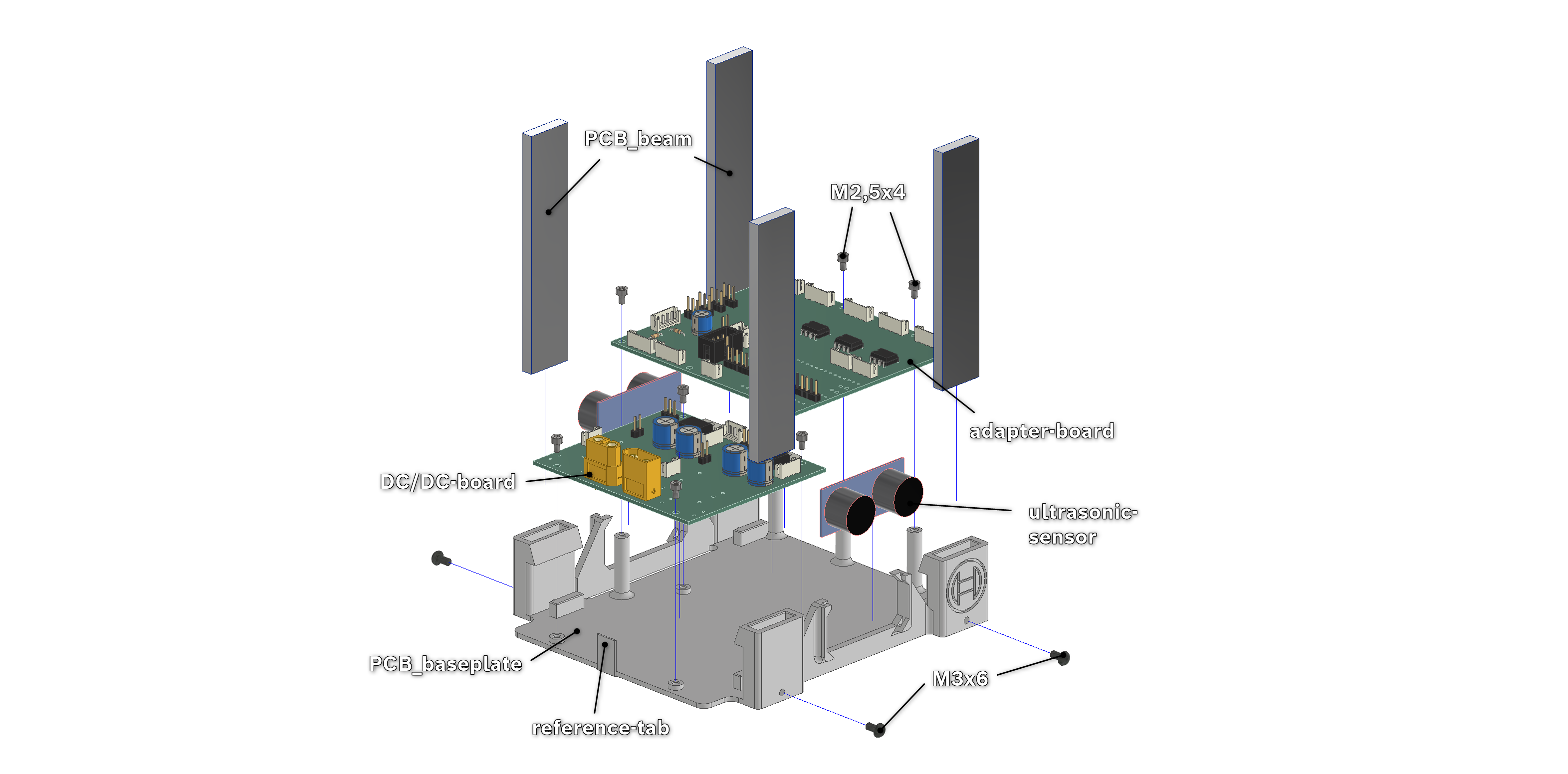
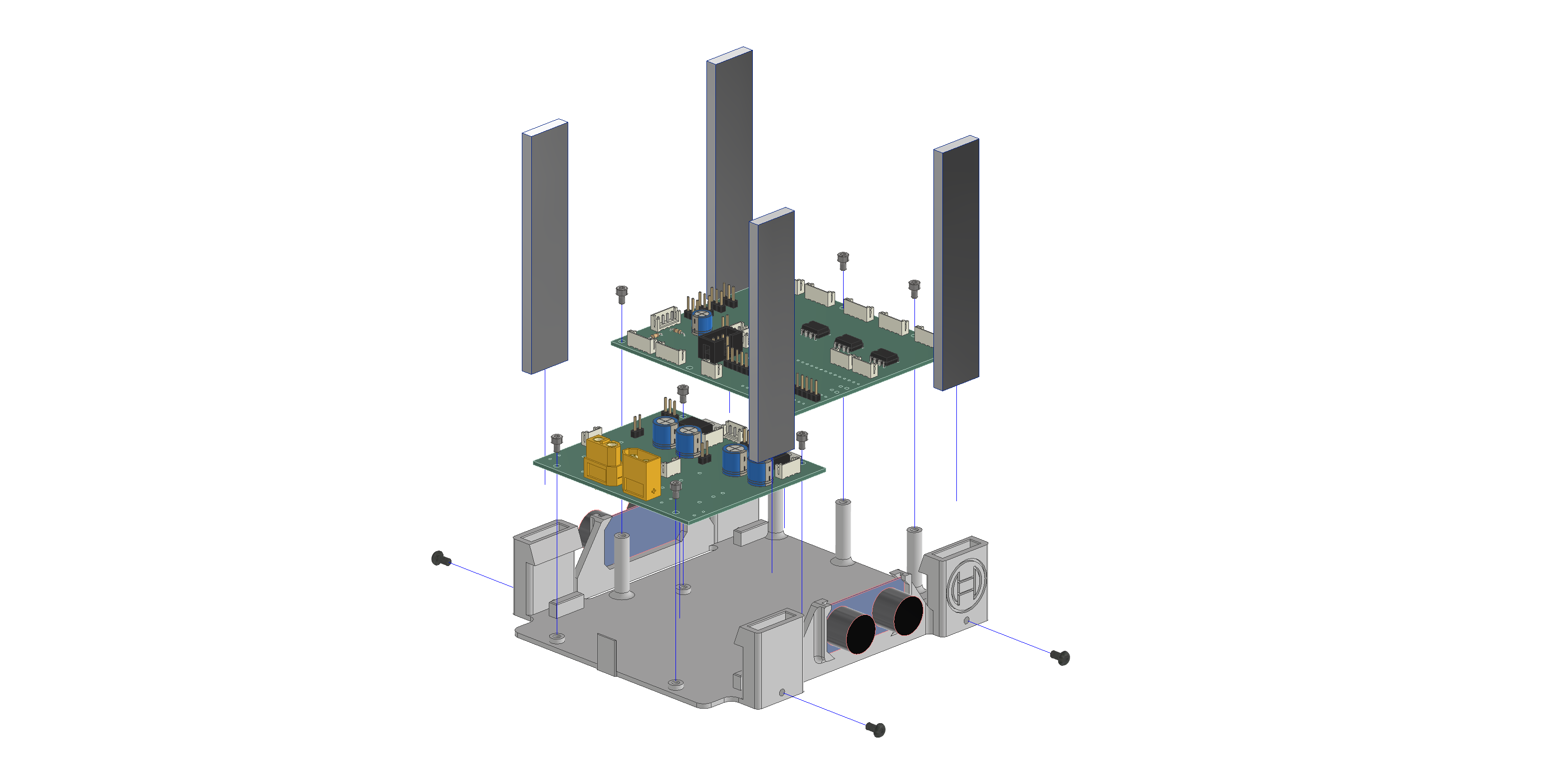
Try to push an aluminium extrusion into the pillars. If there is notable resistance, clean the insides of the pillars of any irregularities until the extrusion can be inserted and removed smoothly, then pull them out again and lay them aside.
Now insert the USS into the side-mounts. This is easiest done, by bending the whole baseplate, but be careful not to over-bend it. The connectors of the USS need to face up, thus, the markings on the sensor are upside down.
Next step is to fasten the DC/DC-board onto the four small mounts on the bottom of the mount, with the yellow power-connectors facing the front/reference-tab. Use M2,5x4-screws for this. Now plug the cables into the board.
Place the adapter-board onto the high pillars, with the row of connectors at the back. Fasten it also with four M2,5x4-screws.
Now push the PCB-beams into the pillars and lock them in place via M3x6-screws, screwed into the sides of the pillars.
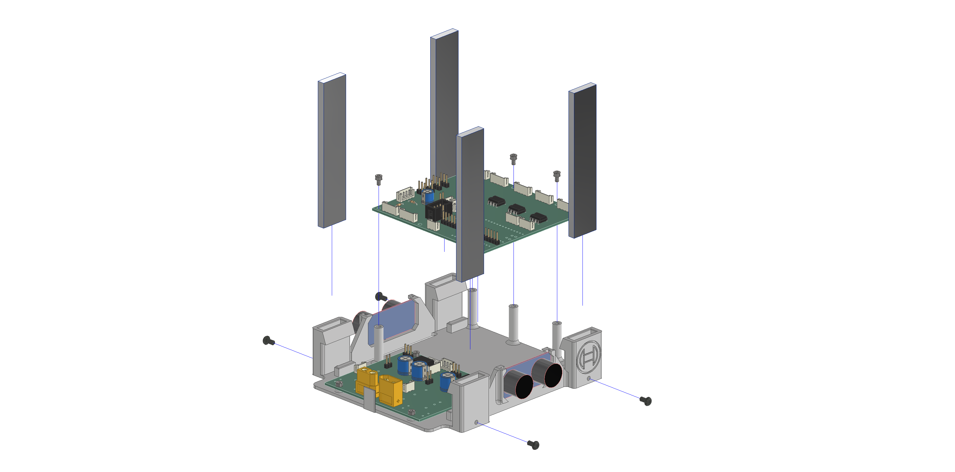
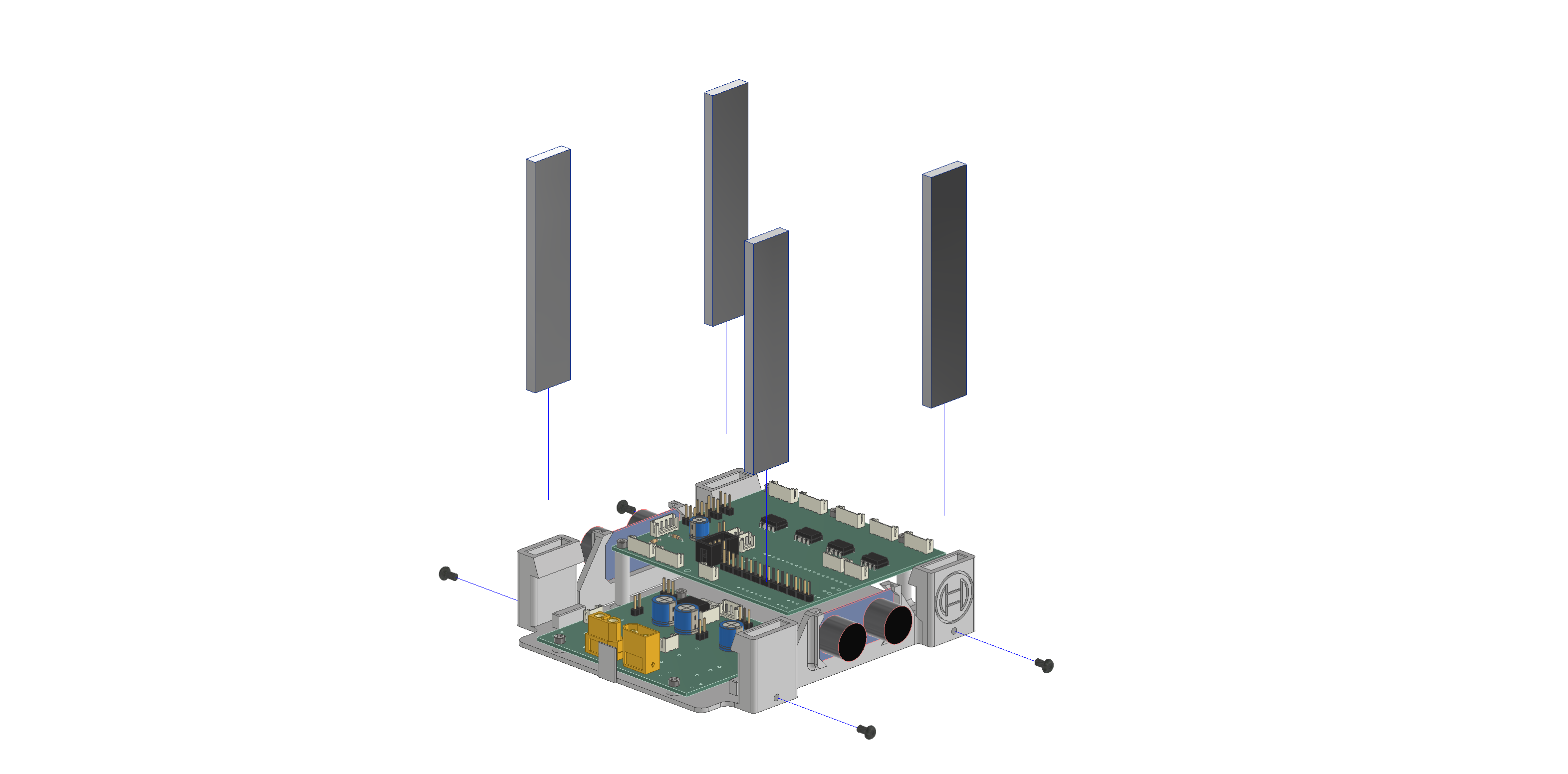
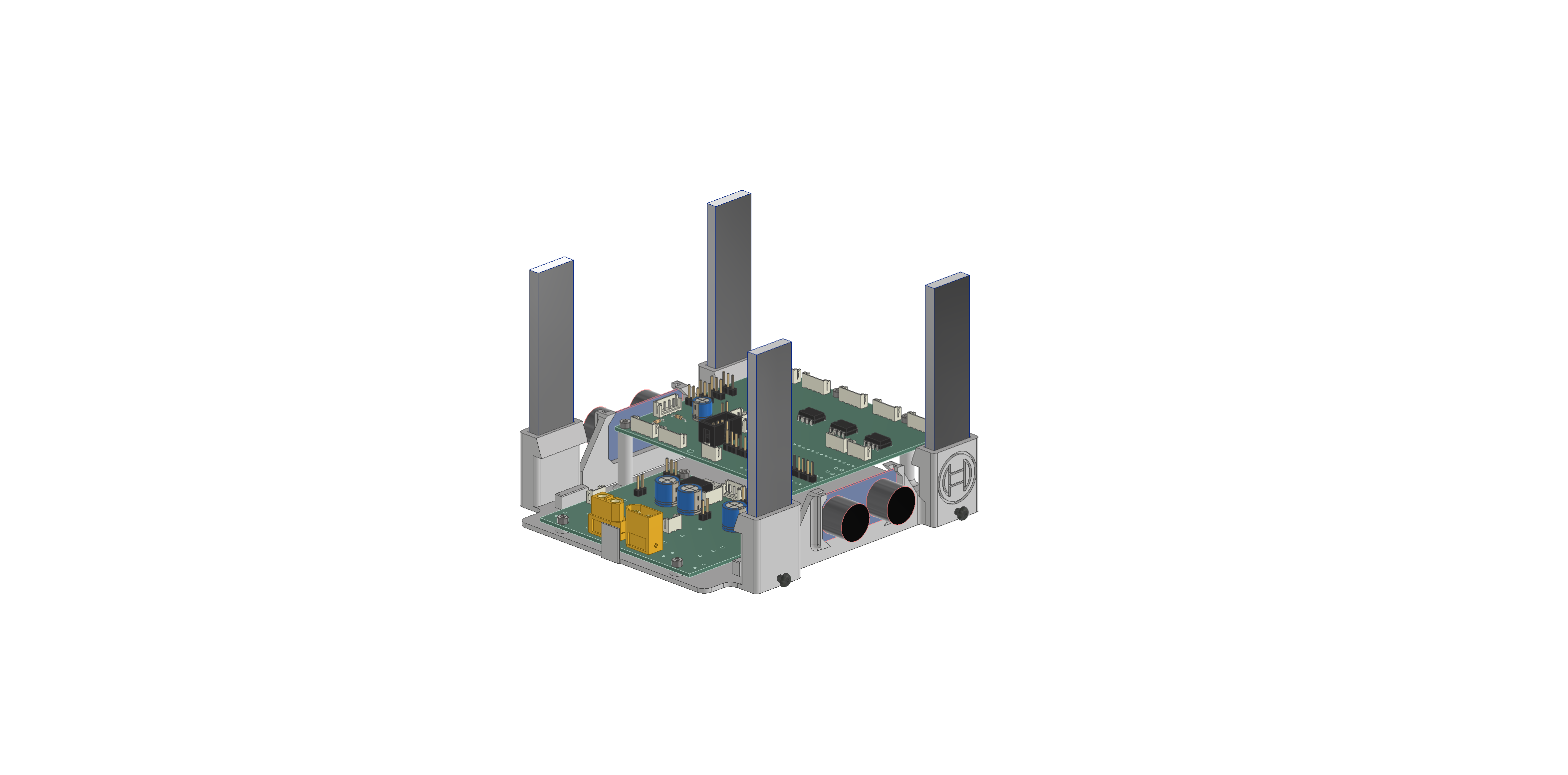
PCB_topplate
Start by once again cleaning out the four pillars on the side, making sure the alu-beams can be pushed through smoothly.
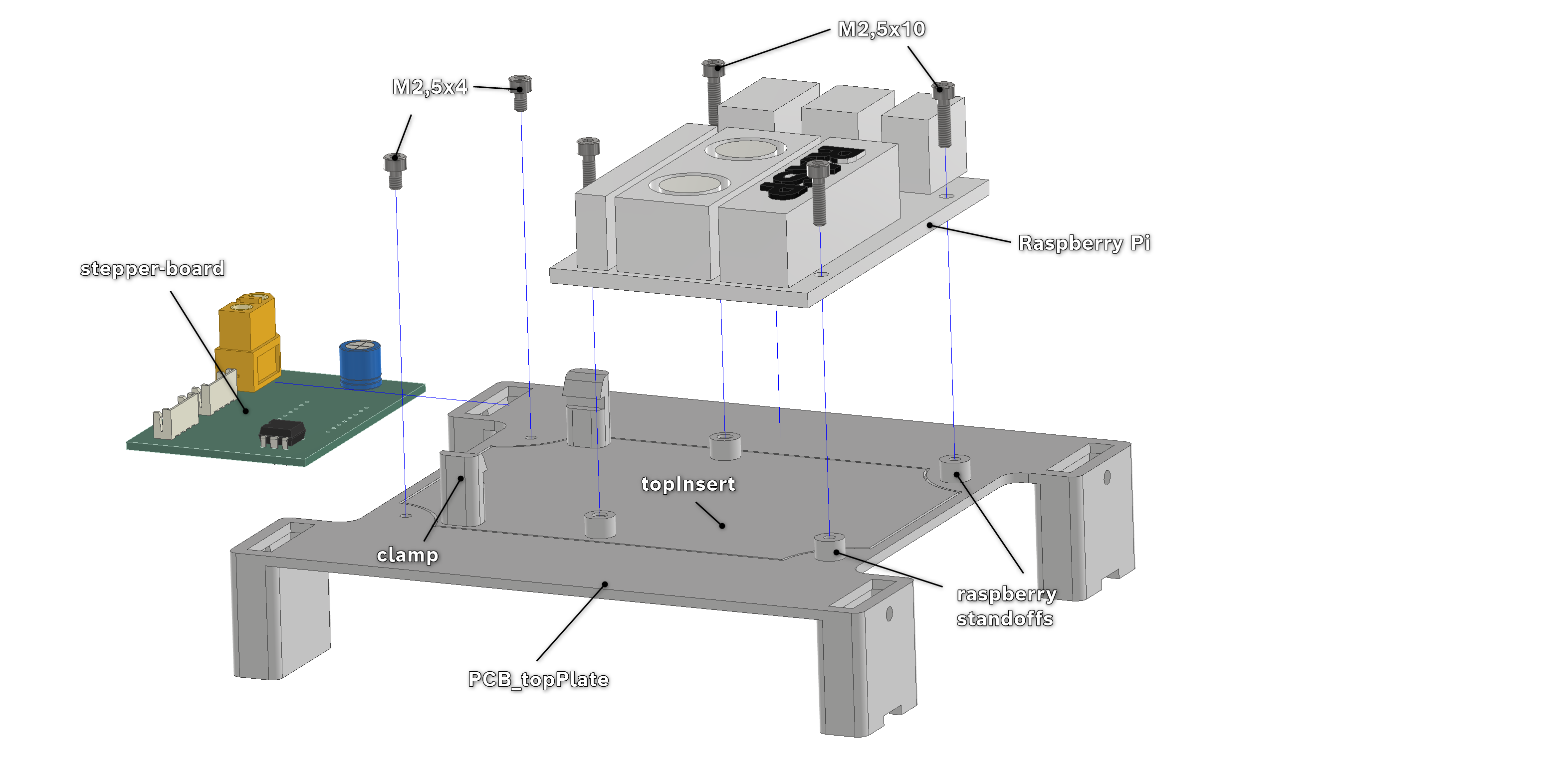
Now push two M2,5x10 screws through the most outer side of the Raspberry and screw the raspberry-standoffs to its underside.
Then push the topInsert (orientation doesn't matter) through the bottom of the topPlate and fasten it with two M2,5x4-screws on the side where the clamps are. On the other side use the screws on the Raspberry with its standoffs and screw in the remaining two M2,5x10-screws through the Raspberry. Its headers should be on the inside of the assembly or rather the connectors should face the outside-edges.
Then simply push the stepper-board into the two clamps.
Now is an opportune time to connect the electronics with their respective cables.
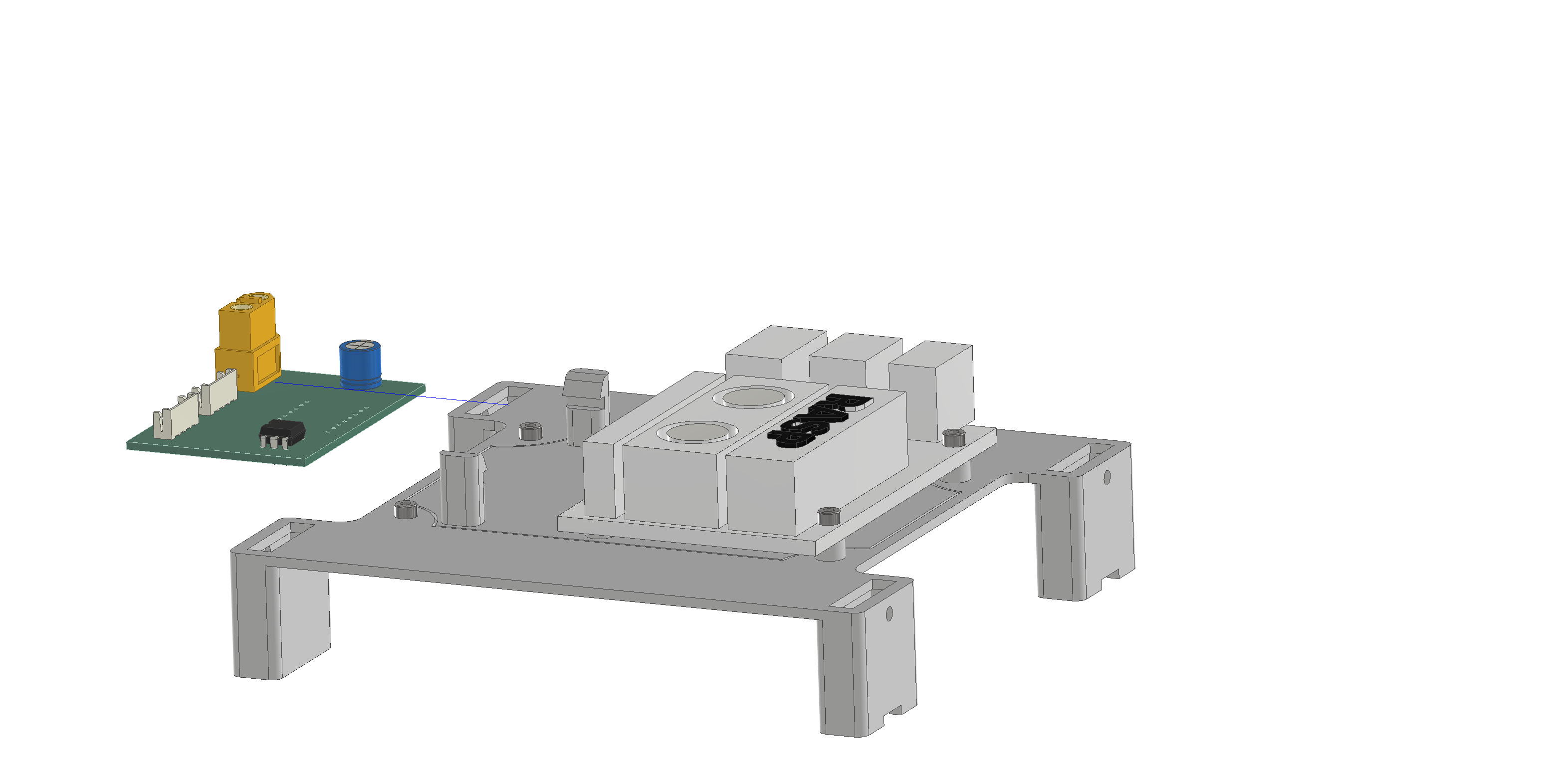
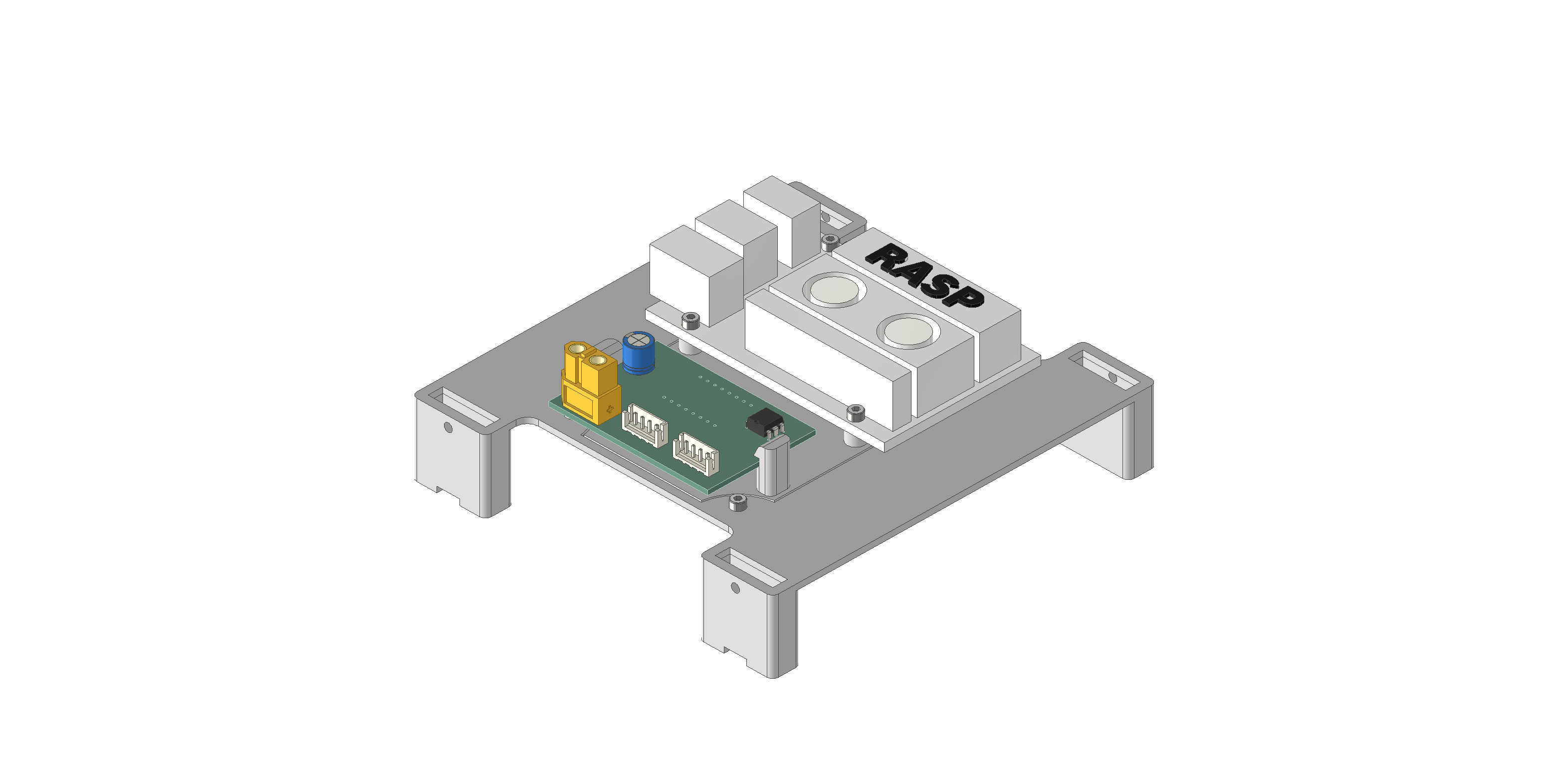
Mounting Plate and its sensors
Start again by cleaning out the pillars on the side of the mounting-plate.
Stick the gyroscope at an angle into the mount (combined_LIDAR_gyro), then lay it flush. Put the strap around it and fasten it with two M3x6-screws. Note that the strap has to lay on the bare PCB → orientation.
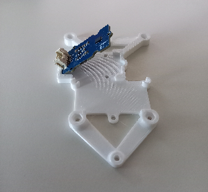
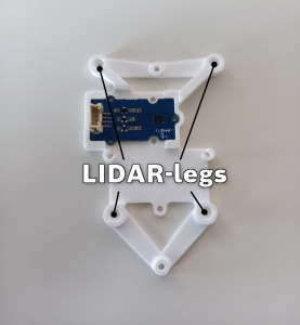
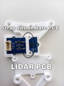
Now place the LIDAR-PCB into its respective slot on the combined LIDAR-mount and fix it in place via its lids and M3x6-screws.
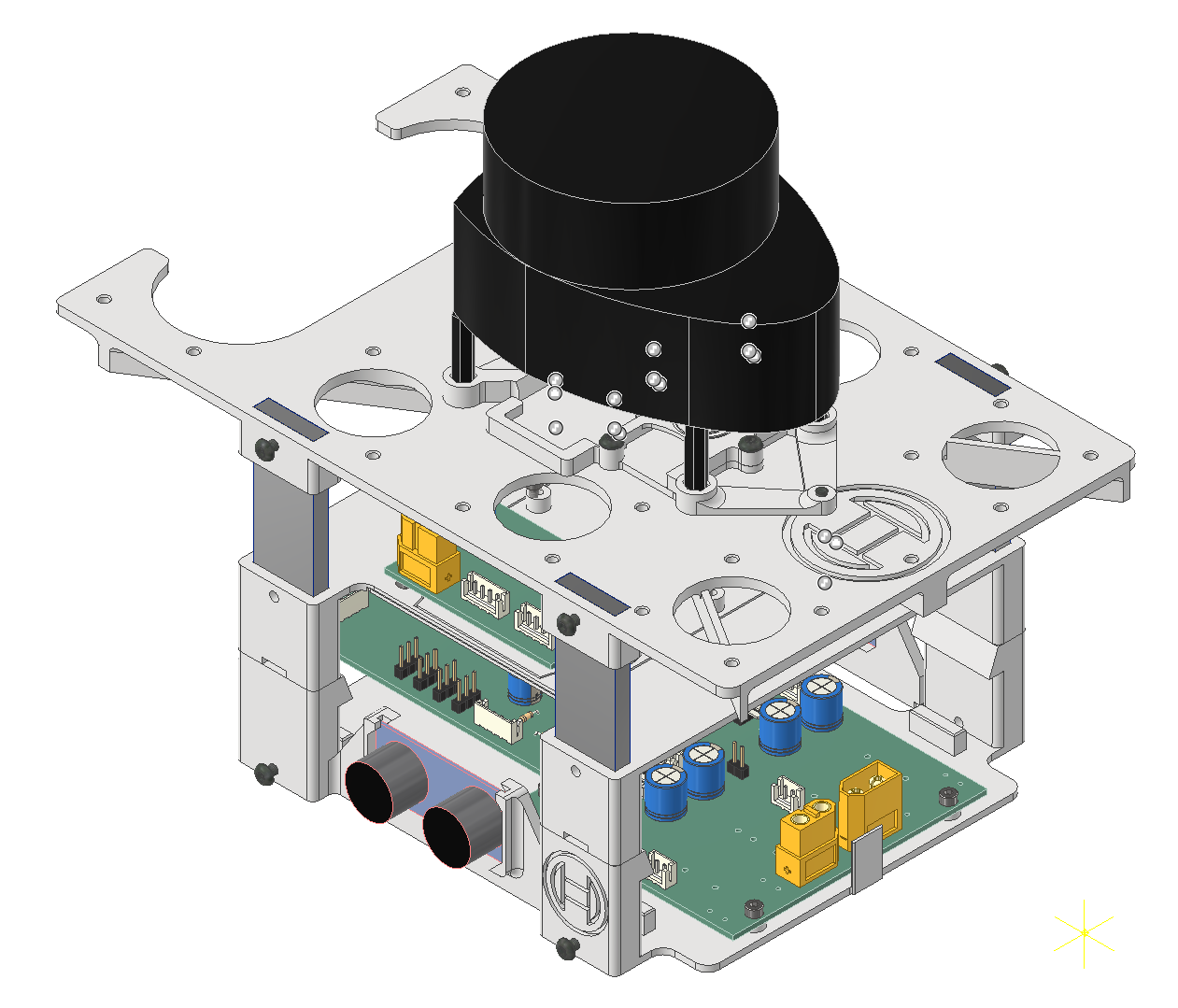
Remove the legs of the LIDAR (so that you have four separate legs and the "actual LIDAR"), then push them into the hexagonal slots of the mount, fastening them with M2,5x8 from the bottom side of the mount. Make sure the screw-heads are fully inside the mount.
Now you can place the mount over the mounting-plate and fasten it with two M3x16-screws from the bottom to the plate (see in the added images which holes to use for mounting). Connect the necessary cables to the gyroscope and LIDAR-PCB, then fasten the LIDAR-unit to its legs again.

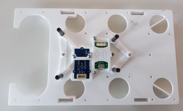
With that done, simply push the mountingplate onto the rest of the PCB-stack with the oval hole facing the backside. If needed, you can again fasten the plate with M3x6-screws screwed into the side of its pillars.
Chassis
Battery-mount
Before you can assemble this mount, you need to manufacture the electrical contacts for the battery. You can also skip this step in the meantime and continue with the guide.
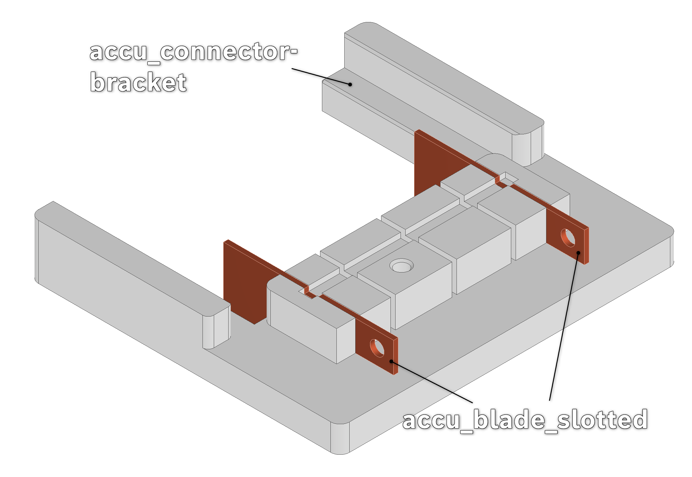
Manufacturing proposal of the accu_blade_slotted
Manufacture at least two accu_blade_slotted out of a 1mm thick copper-sheet. You can print out the attached pdf with a stencil which you can glue onto the sheet.
Depending on what tools you have access to I propose the following technique:
If available punch out the Ø3-hole. Otherwise drill it out but be careful as to not cut yourself.
Cut out the shape of the blade, except the slot, with either a pair of pliers or a saw
File out the slot. Frequently test the fit in the accu_connector-bracket (see later). The less the blade can move inside the accu_connector-bracket, the better.
Schematics:
Assembly of the battery-mount
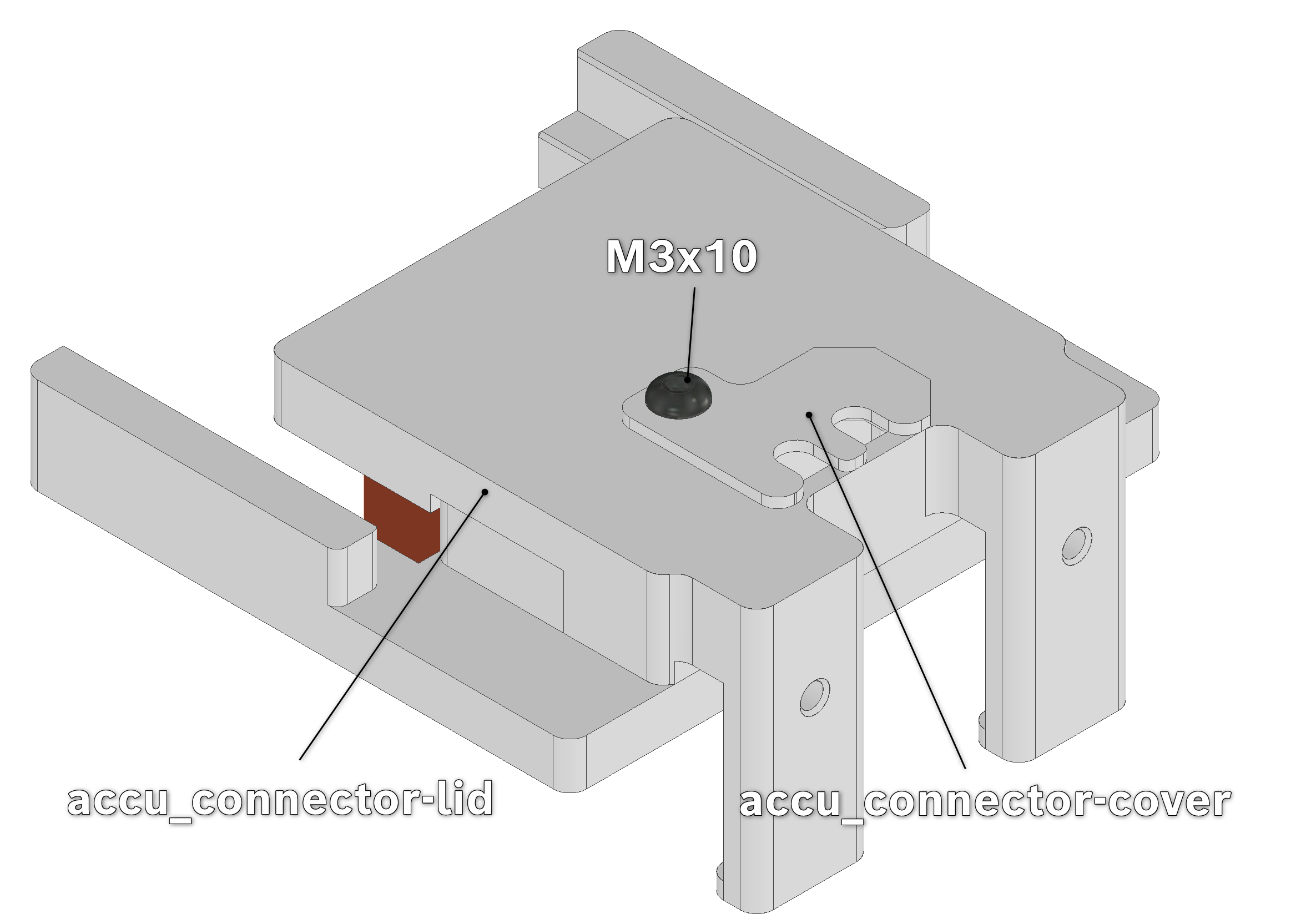
Take two accu_blade_slotted and connect and cable to them (7.2.11. Supply_Battery2DcDcPCB). Then push them into the outer slots of the main-body/bracket of the accu_connector, clamping them down by placing the lid on top and screwing everything together (with the cover-flap) via a M3x10-screw .
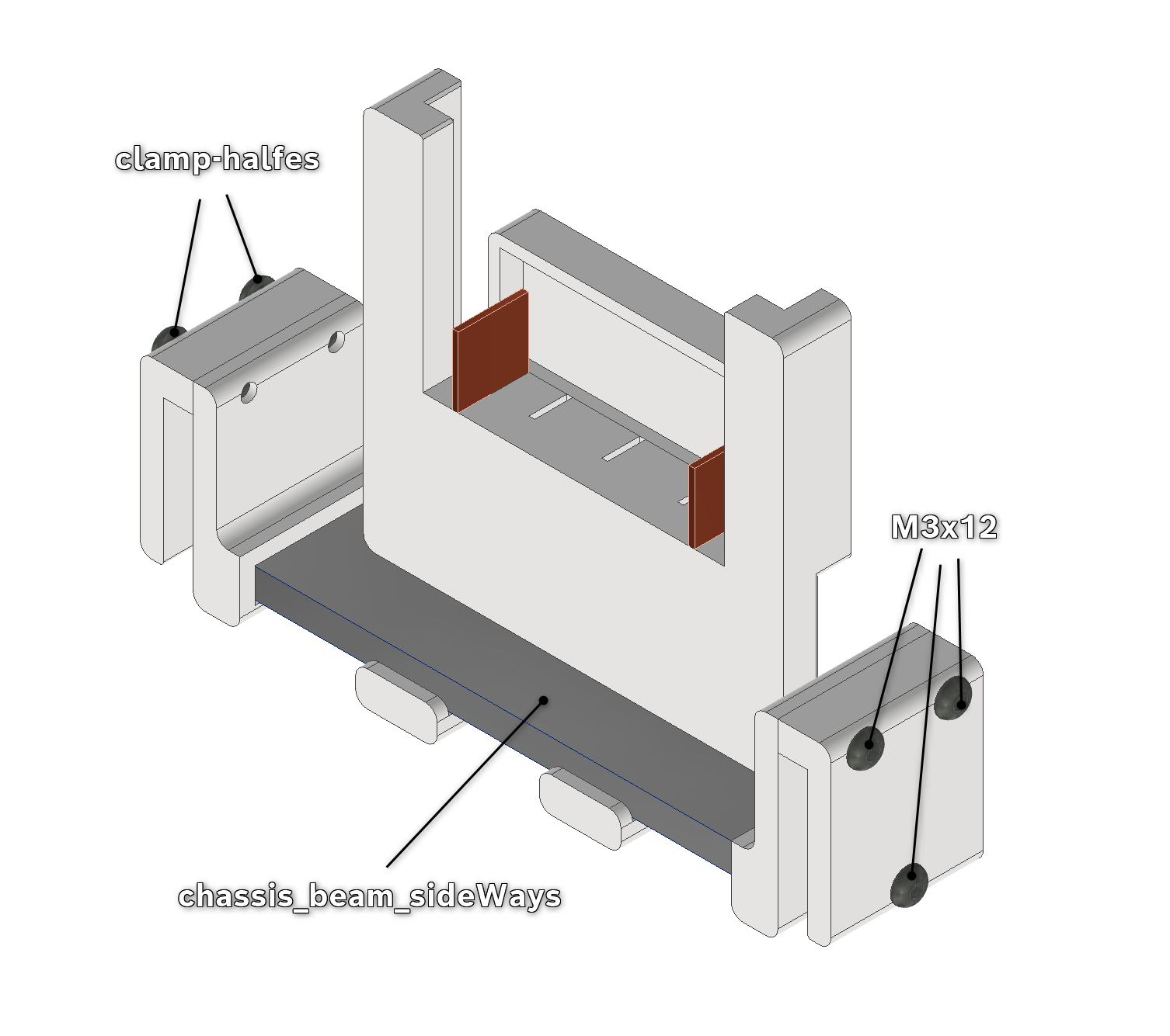
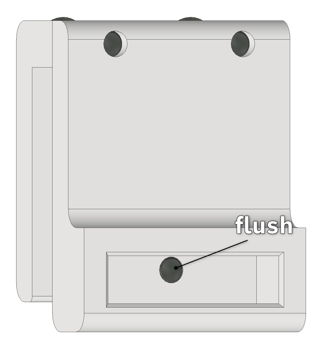
Take the two halves of the chassis_beam_clamp_sideWays and screw them together on the top (M3x12). Also put in a screw at the bottom until it lays flush with the inside-slot of the clamp (see image). Push both assembled clamps onto the axle_beam_sideWays.
Snap the battery-mount onto the alu-beam somewhat centred and screw two M3x6-screws into the bottom of the prongs, but don't tighten them yet! Be careful as to not snap the prongs off.
Lay the assembly aside for now.
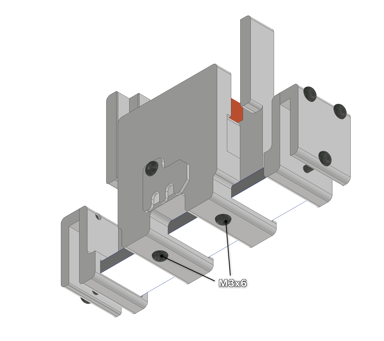
Building the frame
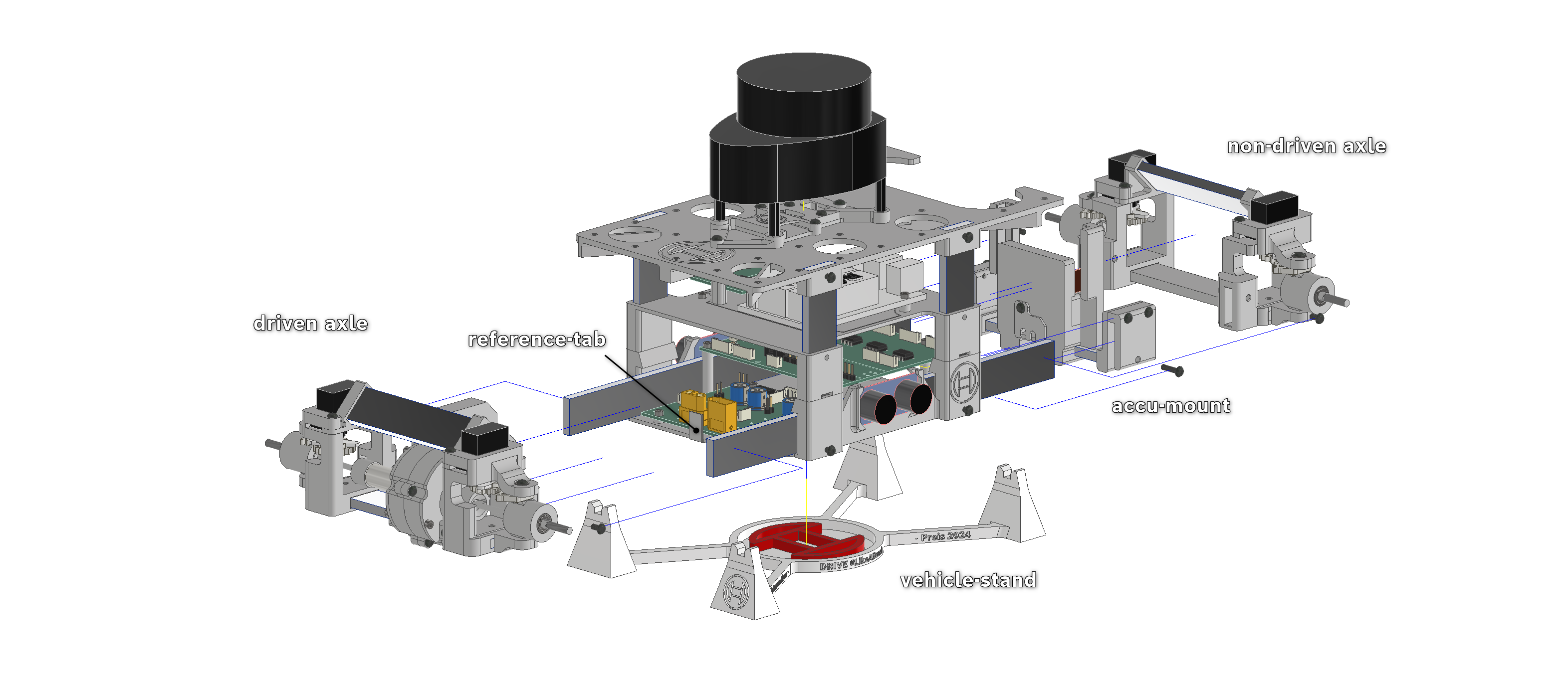
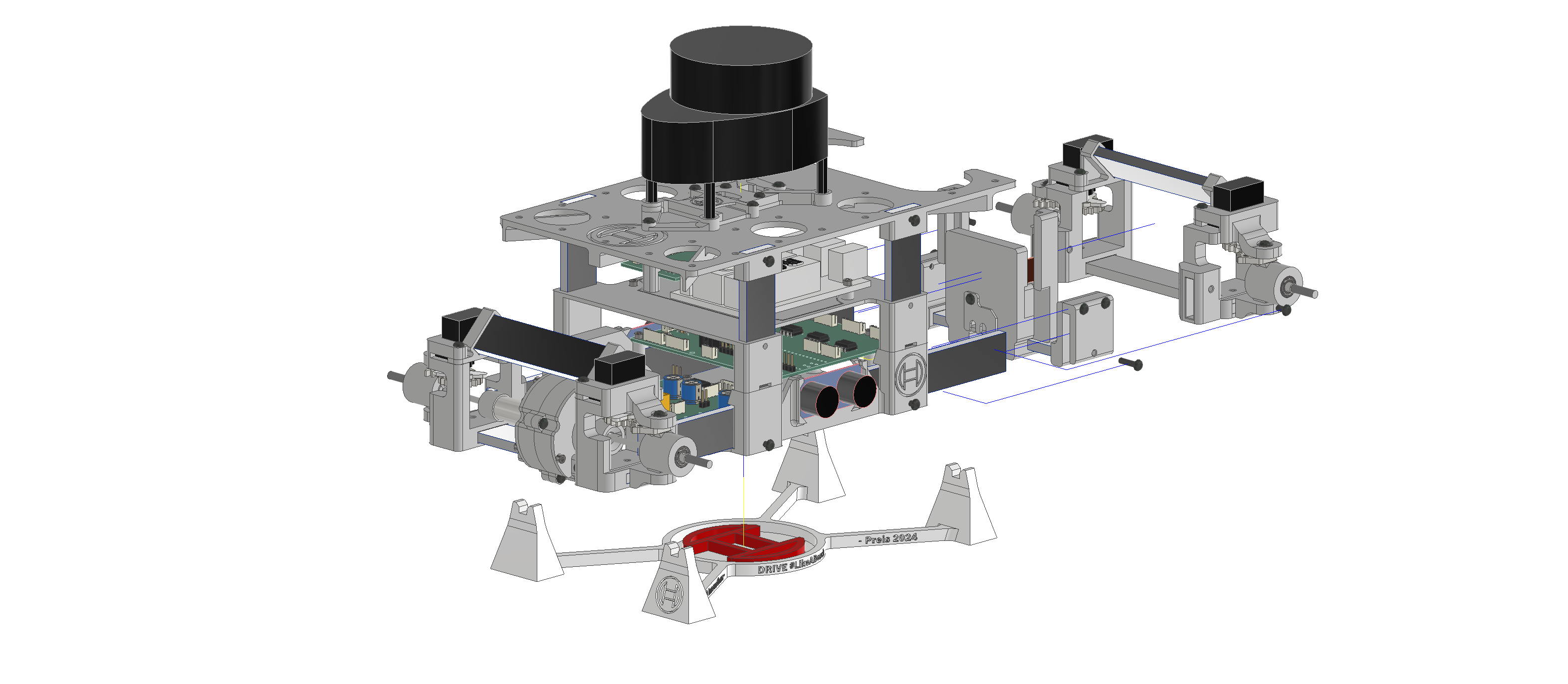
With all the previous preparation, building the frame is simply pushing all the assemblies together.
Take the two chassis_beams and stick them upright through the assembled PCB-stack.
Now push the beams into the axle_beam-ends of the driven axle. If they slip out easily, you can fix them in place with M3x6-screws. Push the PCB-stack forwards until the reference-tab of the PCB_baseplate touches the stepper-motor, but be careful as to not break it off!
Push the previously assembled battery-mount onto the PCB-beams but don't tighten it just yet.
Push the axle-nonDriven onto the other end of the beams, the same way you did with the axle-driven. If you have it printed you can now place the vehicle on its stand.
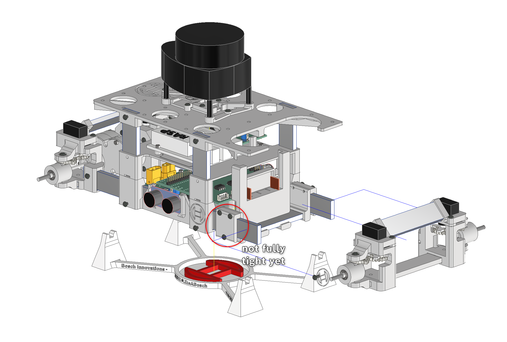
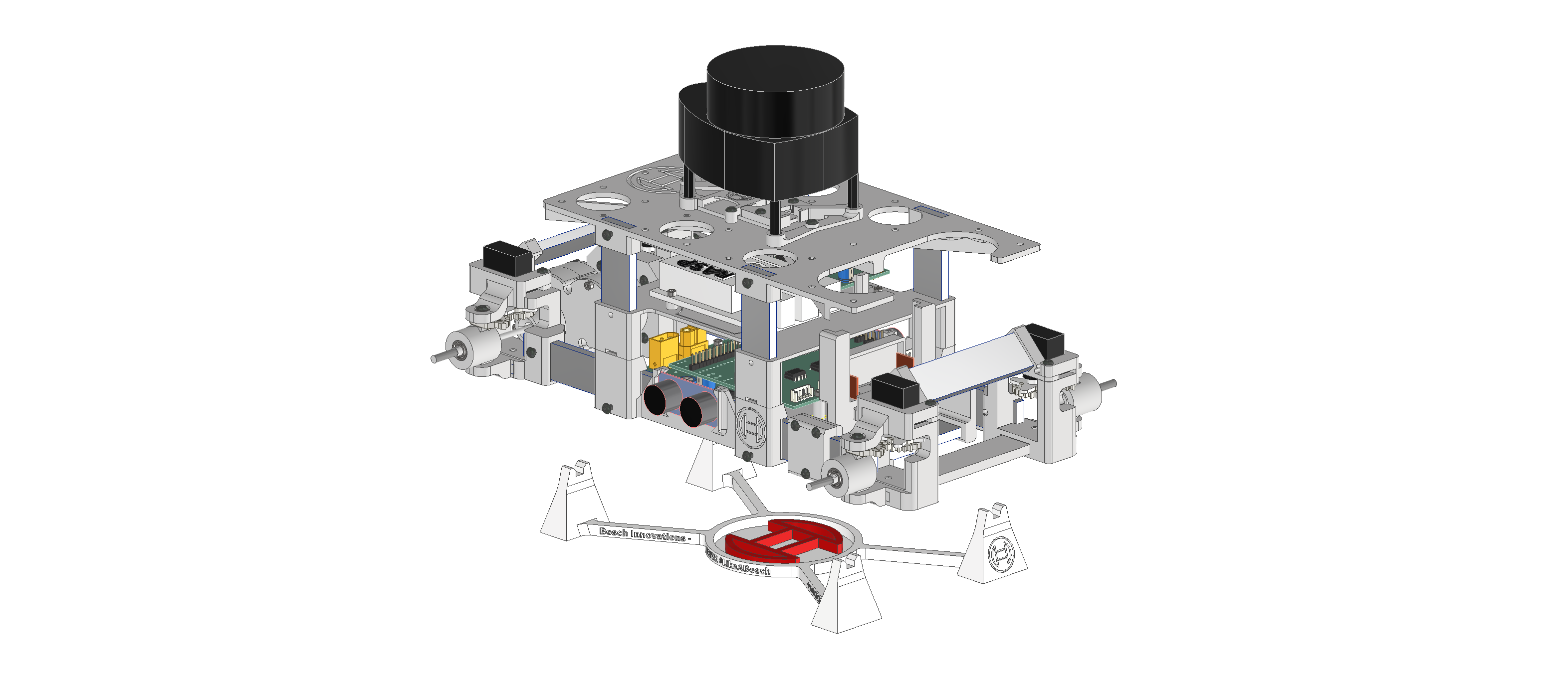
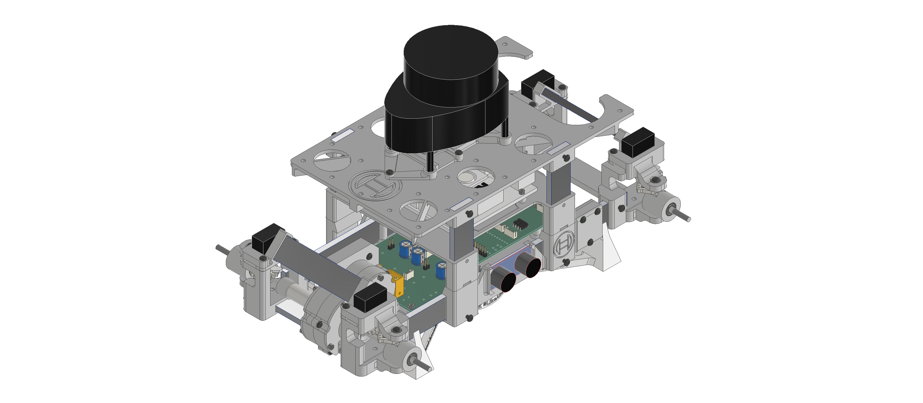
Push the battery into the accu-mount moving around the mount so that the battery fits int o the oval space of the mounting-plate. The battery should also lay flat against the mounting-plate, with its locking-cam snapping under the mounting-plate. Now you can first tighten the upper two screws of the sideways_clamps and then carefully the two screws in the prongs of the mount. If the whole beam slides around inside its clamps, you can tighten the lower screws of the clamps.
Finishing the vehicle
Finally, prepare the mountings for the following components:
Front and rear USS
Pi-camera (optional)
Front and rear USS
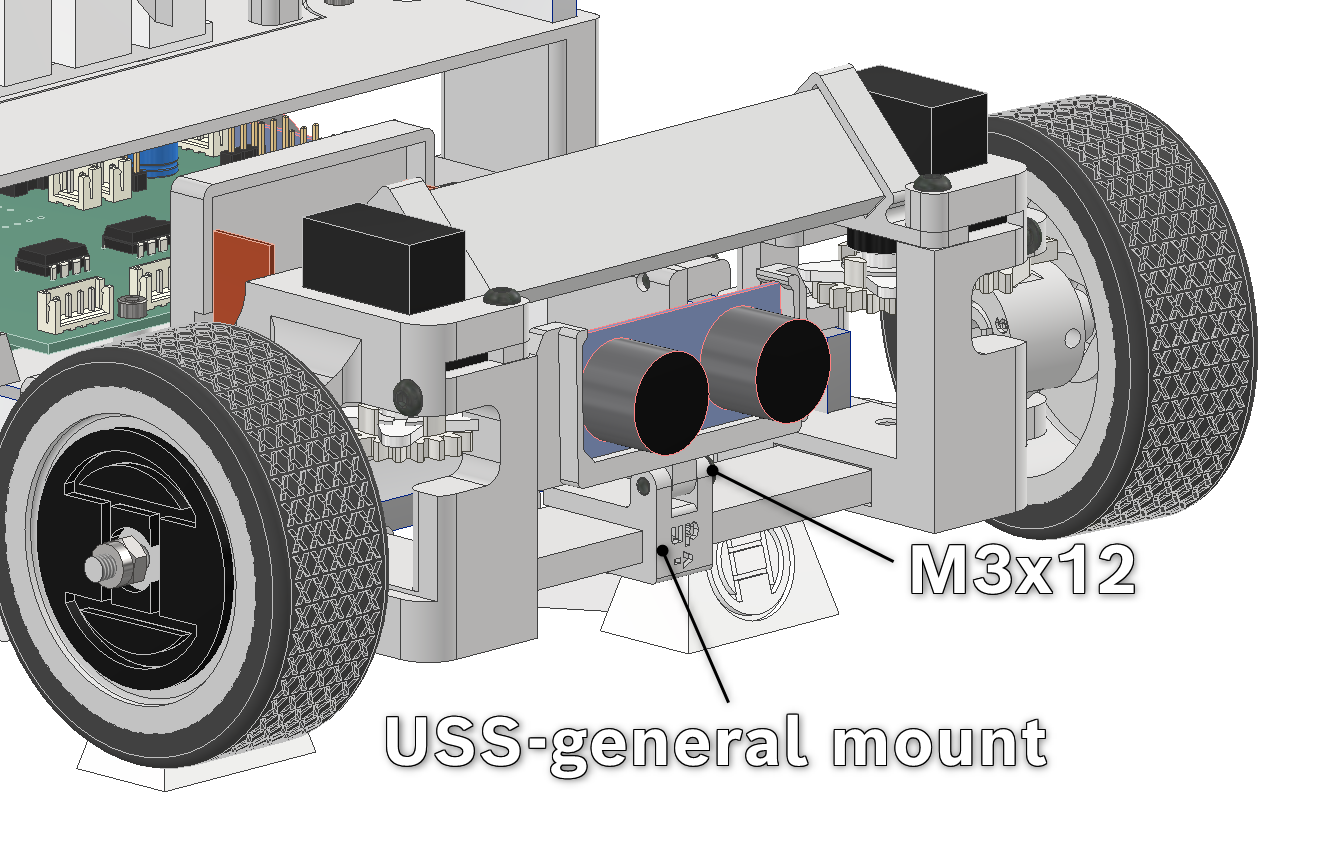
For the (rear) USS-mount, push the USS into the frame with its connectors facing the open side of the frame. Fasten it to the clamp part (M3x12). Make sure you push the screw in through the side where the arrow points "up". Now you can simply push it onto the bottom beam of the non-driven axle.
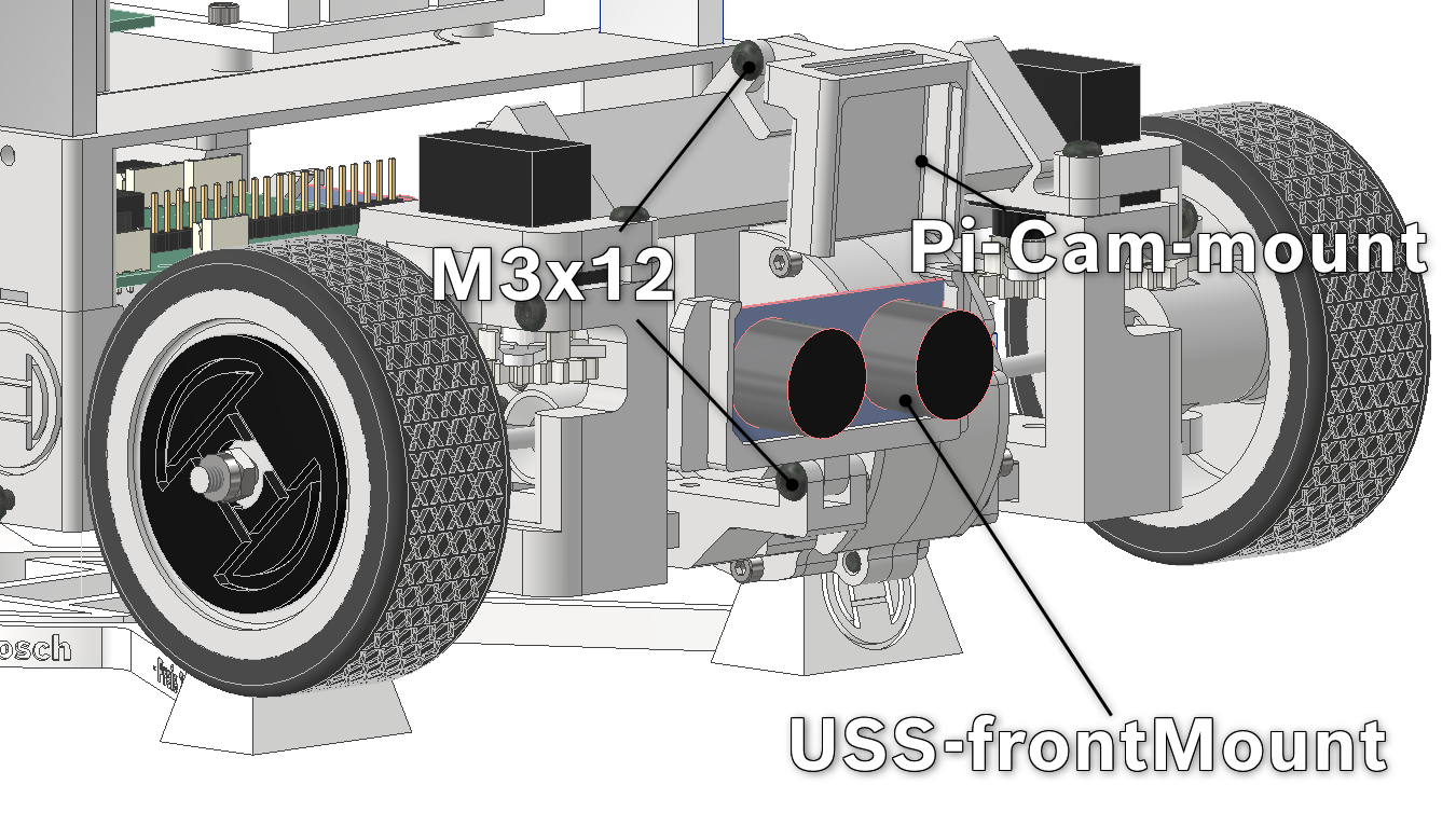
You can do the same for the USS on the front with the exception that the clamp is longer so that the sensor is in front of the axle.
Pi-Camera (optional)
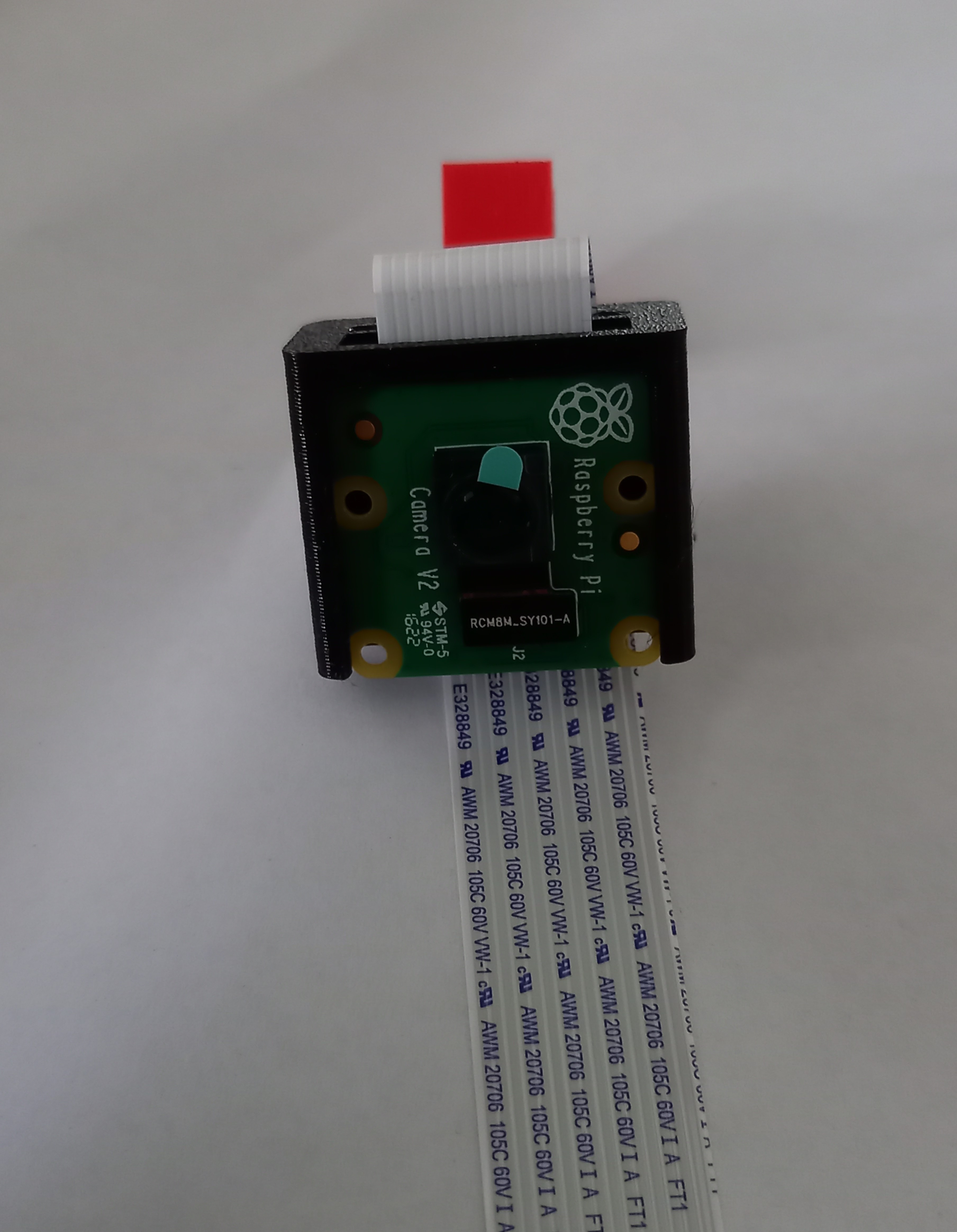
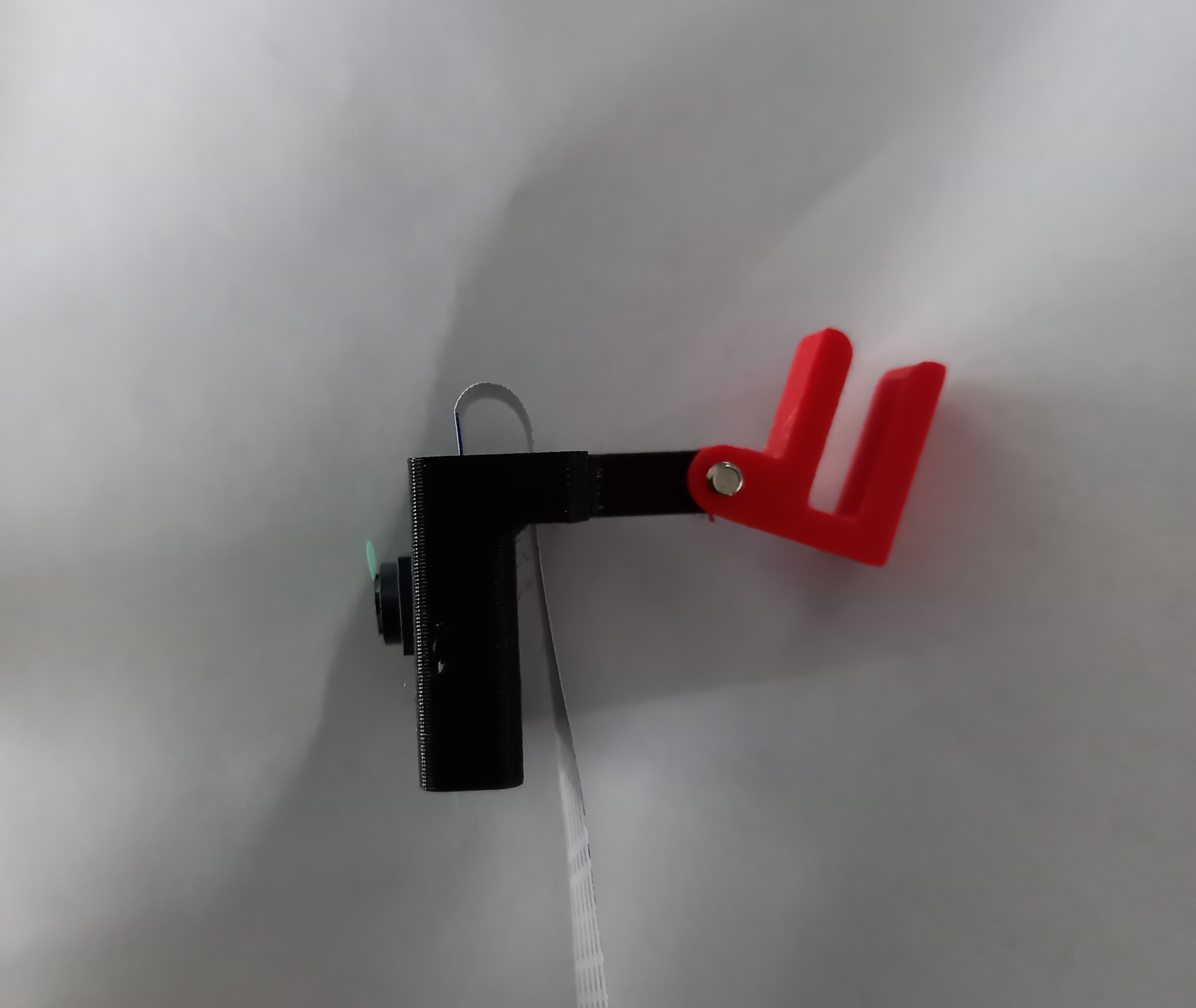
As an optional module, possibly helpful for specific use cases, you can mount a Raspberry-Pi camera V2.
Simply slide the camera with its cable into the mount, pushing the cable out the topside and sliding it back down through the slit slightly behind the camera. You can mount it anywhere on any aluminium-beam or also the mounting-plate (different clamp-version with a smaller gap). The hole on one side (marked with an arrow) has a bigger diameter. Through this hole, use a M3x12-screw to fasten the clamp and mount together. In case the clamp slips of its mount, you can hold it in place with a M3x6-screw screwed through one of the faces of the clamp.