ESD Car 2.0 - Software Documentation
Last steps - SW resources at RPI5
It is recommended to setup the RPi5 based on the install guide ESD Car 2.0 - Raspberry setup, and after reading the ESD Car 2.0 - System architecture and Introduction to the Software you will have and basic overview about ROS (Robot Operating System). The environment will be available after installation, the ROS-workspace needs to be created by the user.
It's also the point in time when you can mount the raspberry pi 5 to the ESD Car, if it's not already done.
To get familiar with basics of ROS, have a look at https://docs.ros.org/en/jazzy/How-To-Guides.html.
Create ROS-Workspace
Copy and clone relevant packages into the workspace
test run a ros command to the car
do the calibration
run the car
For the communication with the ESD Car two options are available:
via SSH: you can access the RPI5 in the vehicle and run commands on the car itself.
via ROS-messages: you can send and receive commands from an other device (e.g. laptop) running the same ROS environment.
Create workspace
To be aligned with the path setting from the rpi5_install script it is recommended to call the folder for the ros workspace "ros2workspace"
To learn how a ROS workspace works and how it is used check this tutorial - https://docs.ros.org/en/jazzy/Tutorials/Beginner-Client-Libraries/Creating-A-Workspace/Creating-A-Workspace.html
rpi5@vehicle20:~$ mkdir ros2workspace #create ros2workspace, for build and run your environmentrpi5@vehicle20:~$ cd ros2workspacerpi5@vehicle20:~/ros2workspace$ mkdir src #create src folder to build the prepared packages and your sourcesFor reference see chapter "SW Resources" in the "ESD Car 2.0 - System architecture and Introduction to the Software".
Copy the provided packages form the ESD Car DIY-Bundle to the src folder of your ros2workspace:
|
.../software/ rpi5/calibration |
|
.../software/ rpi5/odometry |
|
.../software/ rpi5/motion_test |
|
.../software/ rpi5/ros_custom_msgs |
And clone the mentioned repos for micro-ros and rplidar to the src folder of your ros2workspace.
After this preparation you can build your ros workspace:
rpi5@vehicle20:~$ cd ros2workspacerpi5@vehicle20:~/ros2workspace$ source /opt/ros/jazzy/setup.bash # to initialize the ROS environment for a buildrpi5@vehicle20:~/ros2workspace$ colcon build --packages-select ros_custom_msgs odometry calibration motion_test # specify one or more packages to build rpi5@vehicle20:~/ros2workspace$ colcon build # run to build all prepared packages and your sourcesFirst check of microROS and interface between RPI5 and pico
Then you need to run the the microROS-Agent) on the ESD Car via SSH:
The microROS how-to guide (https://micro.ros.org/docs/tutorials/core/overview/) to find information about the concept.
rpi5@vehicle20:~$ source ros2workspace/install/setup.bash # to initialize the ROS environment and commandsrpi5@vehicle20:~$ ros2 run micro_ros_agent micro_ros_agent serial --dev /dev/ttyACM0Now you can send a movement to the ESD Car via single command.
Example: The following command drives the vehicle 1m in forward direction:
rpi5@vehicle20:~$ cd ros2workspacerpi5@vehicle20:~/ros2workspace$ source install/setup.bash # to initialize the ROS environment and commandsrpi5@vehicle20:~/ros2workspace$ ros2 service call /Pico/Motionctrl ros_custom_msgs/srv/MotionControl "{id: 1, rostime: 123456, velocity: 200, arc_length: 1000, angle: 0, override: false}"If everything works fine the response shall be recieved immediately and the values are "accepted == True" and "current_queue_length == 1" (or incremented if previous command not finished) - and the car shall move 1m straight ahead.
Calibration of the ESD Car
A calibration of the ESD Car is necessary for adjusting the mechanical tolerances resulting from the assembly and compensating physical sensor deviations.
There are 2 calibration modes available, a basic and an advanced mode. In the basic mode you will be guided to set up parameters of the vehicle and adjust servo and motor control. In the advanced mode its possible to fine-tune the steering and driving of the vehicle.
At first the vehicle will use default values, which are aligned to the build up instructions in this setup guide. During the calibration these settings will be stored in the flash memory of the Pico. If something happens during the calibration procedure, or you mistyped some settings, you can reset the calibration data to the default values.
The calibration procedure can be started with the python script:
calibration_publish.py
rpi5@vehicle20:~$ cd ros2workspacerpi5@vehicle20:~/ros2workspace$ source install/setup.bash # to initialize the ROS environment and commandsrpi5@vehicle20:~/ros2workspace$ ros2 run calibration GuidedCalibrationThis script works with JSON files in the same directory and sends control and data ROS-messages to the vehicle.
Setting Vehicle Parameters
This step is optional and only applies to you if you deviated from the recommended default values for some of the parameters of your car.
The relevant parameters are shown below, if you used the recommended parts and built the car according to the manual you can skip this part, if you did deviate then you have to run the part of the guided calibration script with the option 3, "Vehicle Data".
|
parameter |
description |
default value |
|
wheelbase |
defines the distance between the front and rear axle |
272 mm |
|
trackwidth |
defines the distance between the middle of the left to the middle of the right wheels |
182 mm |
|
wheeldiameter |
defines the diameter of the wheel |
66 mm |
|
wheelencoderpulsecount |
the count of pulses that the encoder produces per revolution |
500 pulses per rotation |
Calibration of the servos
The goal is to have all four wheels aligned to drive straight and evenly steering, thus the procedure needs to be executed for every single wheel.
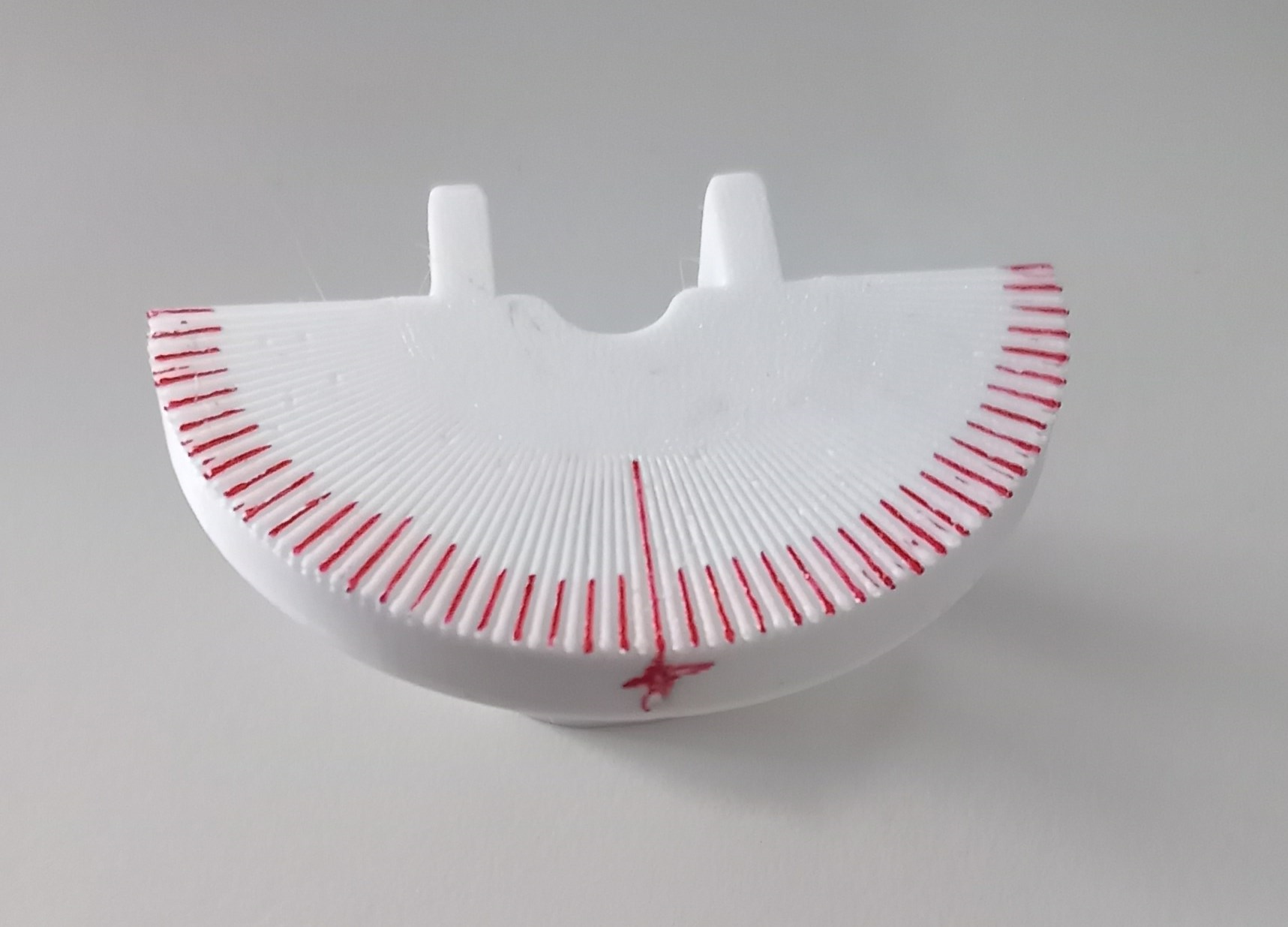
The wheels have to be moved to certain positions per software. In the advanced mode you can use a 3D-printed angle-gauge to easy read the wheel-positions.
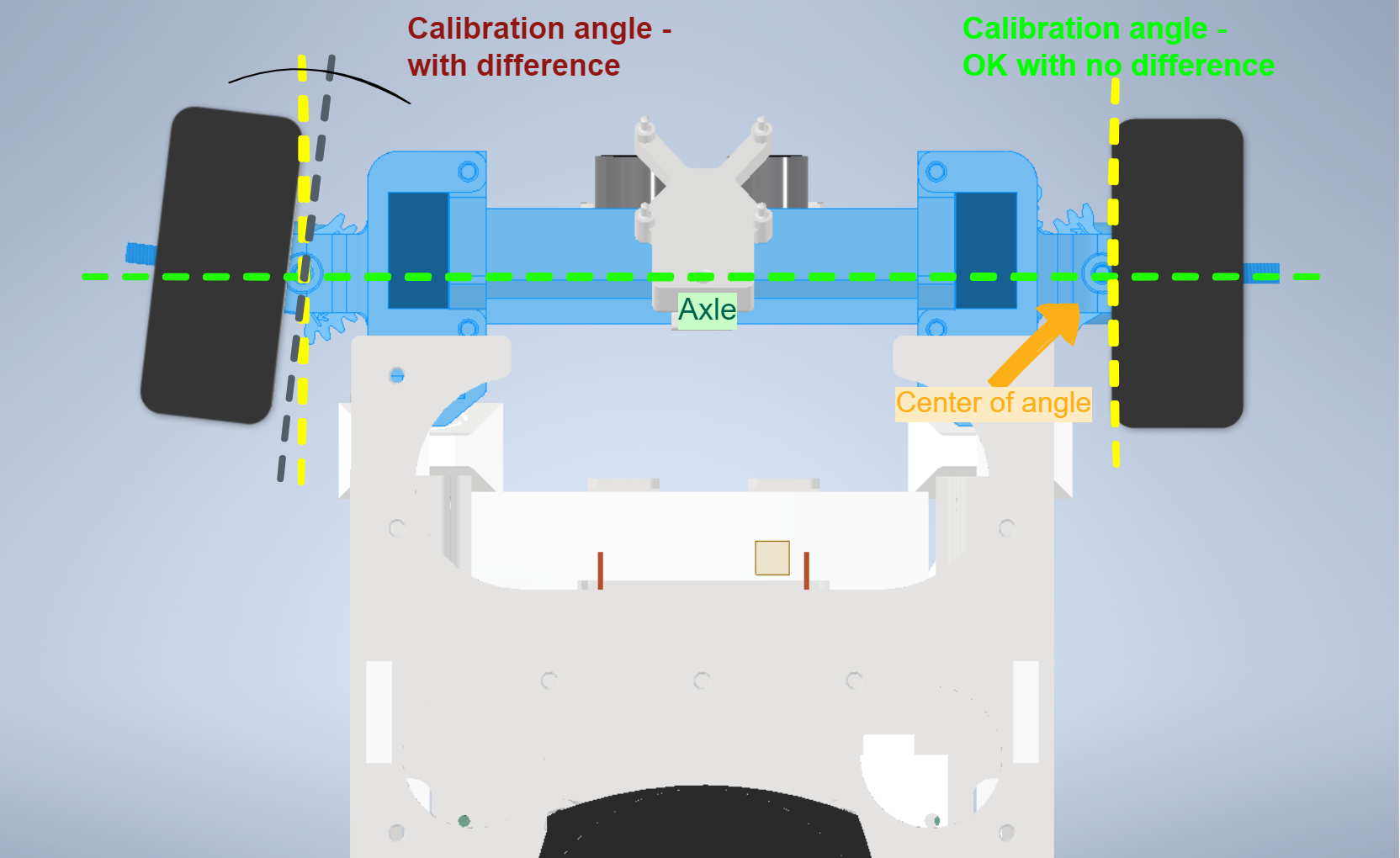
Both basic and advanced calibration guides are described next.
Basic Mode
Neutral position of the servos:
The guided calibration script (option 1, "Servos") will give you the interface to step the angle/position of each of the servos to both negative- and positive angles in order to find the most neutral position (neutral means that the car would drive in a straight line).
Background: this basic calibration only looks for the "d"-part of the y=k*x + d equation and does not care about the min- and max-angles that are possible or the linearity of the servos. It loads default values for these parameters, if you want or have to change them, you can run the advanced servo calibration part of the script as described below.
Advanced Mode
Consists of measuring at least 3 positions for each wheel, recommended is a minimum of 5 positions and is available with the option 11, "Advanced Servos".
The predefined first three positions are the neutral position, the minimum- and maximum steering-angle. The rest are optional intermediate positions.
Background: this calibration both allows you to use the biggest steering angles possible with your hardware (without the wheels hitting any part of the car) and makes sure that the differences in the 4 servos are negated as good as possible (e.g. if you set all servos to -10° in a uncalibrated car some might be at -10°, some at -13° and some at -8°). This is taken care of by both the k- and d-values which will be stored in the flash-memory of the pico which runs the uROS part of the ESD.
The calibration script will guide you through the following steps as good as possible in the console.
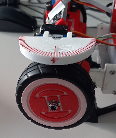
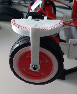
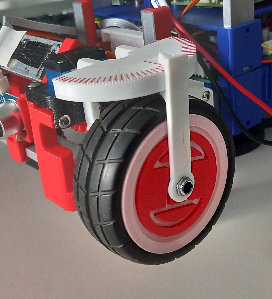
Attaching the angle-gauge
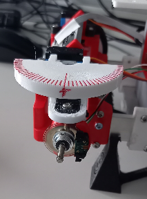
Remove the wheel-nut and wheel. Then simply push the wheel_calibrationScale onto the axle_beam-ends. It is helpful if you paint every second beam, before you mount it. Now mount the wheel and wheel-nut again.
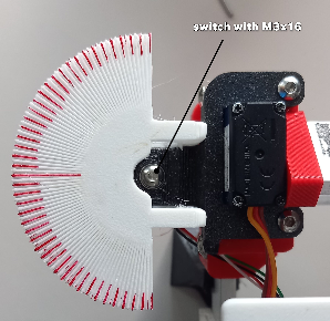
Remove the top screw holding the axle_seat and replace it with M3x16. Screw it as far in until the wheel can't turn anymore.
Now turn the wheel-nut, so the wheel_calibrationPointer, when pushed onto the nut, sticks straight up, then push it on.
You can now use the scale to measure the wheel turning up to 2° accuracy. Make sure that once you are finished with calibrating, the M3x16-screw gets switched back to M3x12.
Setup of neutral position
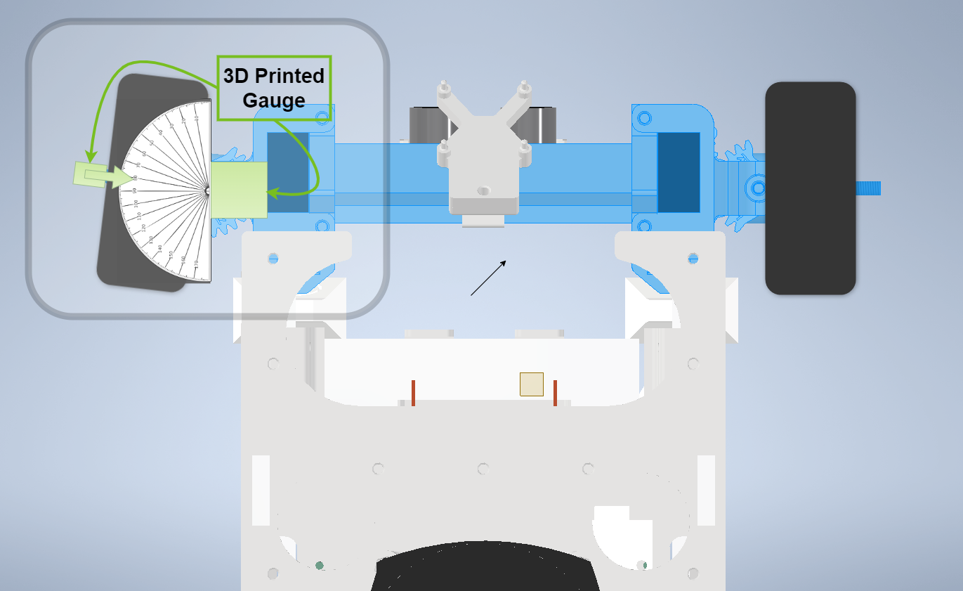
Attach the 3D-printed angle-gauge to the axle, it will help you to find the exact neutral position (0° steering).
The script will guide you to position the wheel to the 0° marking (=neutral) on the scale of the angle-gauge. If the position is reached, the values shall be stored.
Minimum and maximum steering-angle
Take care to have the wheel mounted on the axle for this first step, because the maximum angles may depend on the type of wheel you are using.
Position the wheel to the maximum angle that allows the wheel to spin free. Do this for the topmost left - and right position. The script will guide you through the procedure.
Setup of intermediate positions
To increase the precision of the calibration, it is recommended to measure some additional positions between the end-positions, e.g. in steps of 10°, using the already axle-mounted angle-gauge:
Position the wheel to these intermediate angles (e.g. -30°, -20°, -10°, +10°, +20°, +30° on the scale of the angle-gauge). Repeat this step at least 2 times, approaching every angle both from the right and the left. The script will guide you through the procedure.
Calibrate distance measurement
The option 2, "Motor", part of the guided calibration script aims for both checking and correcting the values of the wheel-encoder input. In order to do this the car will drive a certain distance (e.g. 1m) with a low velocity and stops when it thinks that it drove exactly that distance.
The recommended way of performing this is very simple, you mark one part of the car at the starting position (e.g. put a piece of tape down at the middle of one of the front wheels), then you start the script, let the car drive the distance, put another piece of tape down where the front wheel is now and measure from the first tape to the second tape. This measured value is the input for the script in order to calculate the error in the overall system.
Background: this only calibrates the diameter of the wheel because the type of wheel encoder always give a fixed amount of pulses per rotation. The stepper motor, gear ratio, microstepping etc. is not part of this calibration therefore it is not guaranteed that the velocity and accelaration of the car is correct even after doing this. This should not be a problem as long as the error is not too extreme (e.g. you used a microstepping that made the motor rotate 2, 4, 8 or 16 times as fast as expected → very big difference between expected and real speed and therefore problematic).
If the script detects a too big error it will tell you that there might be a problem with the hardware of your car, possible reasons for this might be a loose connection of the wheelencoder or a different wheel diameter, you can still use the car this way but it is recommended that you check the reason for the deviation.
Drive and control the ESD 2.0 Car
Function description of Pico SW
Motion Control
The basic function of the Pico SW is to receive the motion-control commands from RPI5 and drive the ESD Car. The software contains a library for ROS2 communication with an microROS-client via serial-USB-port, and other libraries for sensor inputs and controlling the outputs.
After power-on or reset the software will initialize the car and calibrate the gyroscope, which last for approximate 2 seconds . It's recommended not to move the car during this time. The running state of the Pico will be indicated with the blue and green LED. They are blinking when the scheduler of the operating system is running.
When the Pico SW is running, then also ROS messages are sent with the current vehicle data. With that you can check the alive state and derive data for calculation of the odometry of the car. It is also ready to receive commands to start driving.
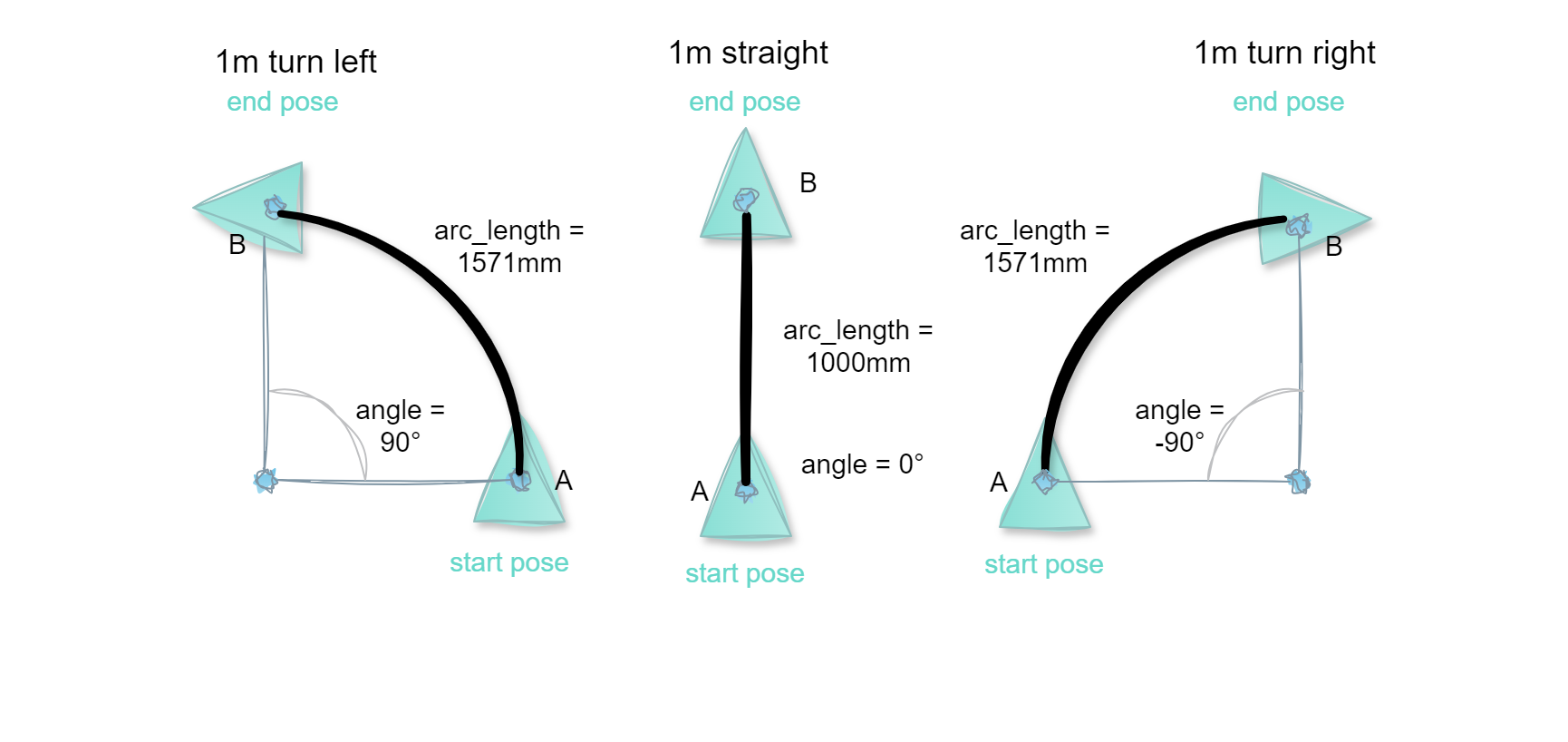
The commands need to be published in the ROS2 MotionControl.srv service. Please note that the drive direction is in mathematical turn order, i.e. positive angle turns counter clockwise (left) and negative angle turns clockwise (right).
Example:
Trajectory Controller
The controller works based on the principles of pose estimation, waypoint check, and navigation in its own local coordinate system. It receives sensor data to calculate the vehicle's pose and checks for the next waypoint to adjust steering and throttle. The waypoints are structured with information about the current and next waypoint, while the pose estimation calculates the vehicle's position in relation to its origin. The controller consists of a throttle controller and a steering controller, each with specific functions and control strategies. The steering controller uses the Proportional Path Following strategy to calculate the steering angle based on tracking error and orientation error. The throttle controller, which operates using a PID (Proportional-Integral-Derivative) control method, then uses the specified speed to regulate the throttle.
Since the car is equipped with ultrasonic sensors, it will detect obstacles in the way. If any obstacle is below the safety distance of 15cm, the vehicle will stop moving.
An overview of the available ROS messages for controlling the car was provided in Functional Overview of the Raspberry Pi Pico in the ESD Car 2.0 - System architecture and Introduction to the Software.
Simple movements commands in ROS2
You can move the car with an service call or with the motion test script. This script reads the command.json file and creates a service call, and retries if the service was not recieved properly.
Example: The following command drives the vehicle 1m in forward direction:
rpi5@vehicle20:~$ cd ros2workspacerpi5@vehicle20:~/ros2workspace$ source install/setup.bash # to initialize the ROS environment and commandsrpi5@vehicle20:~/ros2workspace$ ros2 run motion_test motion_test_nodeBasic implementation of receiver for odometry data
The basic odometry node receives the VehicleData message from the Pico and sends TF data (see https://docs.ros.org/en/jazzy/Concepts/Intermediate/About-Tf2.html) of odometry-based localization. This could be used together with SLAM algorithms for map building and improved localization.
Helpful additional resources
Web3, Agents and Distributed Systems
Web3 technologies enable the ESD Car and its infrastructure to implement a plethora of interesting use cases related to decentralization, self ownership and control of data (self sovereign identity) or transactions with the blockchain. Possible use cases in this context could be tolling, parking, EV (electrical vehicle) charging, micro payments etc.
To this purpose, the Fetch.ai framework a decentralized, open-source platform is designed to facilitate the creation and deployment of autonomous agents on a decentralized network. It combines elements of blockchain technology and artificial intelligence (AI), to enable (autonomous) agents to perform tasks, make decisions, and interact with other agents, services, or IoT devices without human intervention.
One example of the Fetch.ai implementation in combination of the Bosch XDK Multi-Sensor Device is described in this article: https://fetch.ai/blog/bosch-deltav-sensor. The corresponding code is provided here: https://github.com/SoftwareAG/cumulocity-xdk-agent.