ESD Car 2.0 - Raspberry setup
Installation of RPI5
The installation of the RPI5 comprises following main steps:
Setup of Ubuntu 24.04-LTS
Installation of ROS2 JAZZY (Robot Operating System - version jazzy)
Installation of libraries and python packages
Adaption of shell initialization and environment variables
The recommended setup for installation is a PC to prepare the SD-Card image and a desktop-environment for RPI5 (USBC-Power supply, monitor, mouse, keyboard) as well as an WIFI internet connection, before you install the RPI5 into the car..
Then follow the official installation procedure for Ubuntu 24.04 LTS for RPI5 (https://ubuntu.com/download/raspberry-pi) until you are able to access the desktop screen.
Alternatively you can select the Ubuntu version in the official Raspberry-Pi-Imager.
In the shell-examples below we used the username "rpi5" and the device name "vehicle20".
Some necessary tools and pre-configuration to operate the ESD Car there is an install script available in the ESD Car DIY-Bundle:
".../software/
rpi5/
rpi_install.tar.gz".
To save the file attributes and linefeeds of the installation scripts the folder is stored as .tar.gz. Just unpack the archive, and run the installation:
rpi5@vehicle20:~$ tar -xzf rpi_install.tar.gzrpi5@vehicle20:~$ cd rpi_installrpi5@vehicle20:~/rpi_install$ ./install.shThe script should have installed ROS2 JAZZY. To verify if installation is OK, you can try this guide to check if you can run it in your desktop environment:
https://docs.ros.org/en/jazzy/Tutorials/Beginner-CLI-Tools/Introducing-Turtlesim/Introducing-Turtlesim.html
It will start a GUI with a turtle symbol which can be controlled via ROS - congratulation when you are able to move it.
To get familiar with ROS2 it is recommended to go through the https://docs.ros.org/en/jazzy/Tutorials.html#
Configuration of Power-supply
The Raspberry Pi 5 (RPI5) is supplied from the DC-DC-board via RPI5-header-board (which is a power-HAT) with 5,25V. The supply voltage of RPI5 needs to initially set via the potentiometer RV1 on the DC-DC-board:
Disconnect the RPI5
Measure the Voltage on supply-Pins
Insert the 18V LiPo battery
Adjust RV1 to set 5,25V
After this, the RPI5 can be properly connected and powered.
To tell the RPI5 this supply configuration via the header some settings in the EEPROMs need to be done, otherwise, there is a power warning and restriction on USB power output. That means for a brand new RPI5 with brand new RPI5-header-board the initialization of the EEPROMs needs to be done.
Instructions and tools can be found here: https://github.com/raspberrypi/hats.
EEPROM of RPI5
1) Check initial EEPROM config with "rpi-eeprom-config" it look like this:
rpi5@vehicle20:~$ rpi-eeprom-config[all]BOOT_UART=1POWER_OFF_ON_HALT=0BOOT_ORDER=0xf4612) Edit EEPROM config with the command "sudo -E rpi-eeprom-config --edit" to the following:
rpi5@vehicle20:~$ sudo -E rpi-eeprom-config --edit[all]BOOT_UART=1POWER_OFF_ON_HALT=0WAKE_ON_GPIO=0PSU_MAX_CURRENT=5000BOOT_ORDER=0xf41For Details to these settings
WAKE_ON_GPIO=0 see for details: https://www.raspberrypi.com/documentation/computers/raspberry-pi.html#WAKE_ON_GPIOPSU_MAX_CURRENT=5000 see for details: https://www.raspberrypi.com/documentation/computers/raspberry-pi.html#PSU_MAX_CURRENT
EEPROM RPI5 Header board (ESD-Power-Hat)
The ESD-Power-Hat has an EEPROM mounted which needs to be initialized and flashed.
See for reference https://github.com/raspberrypi/utils/tree/master/eeptools to setup and install EEPROM-UTILITY Tools.
(Hint: Clone utils git repo from link above)
clone the eepromutils as flashtool
Close the HW the Jumper "J4" on the ESD-Power-Hat
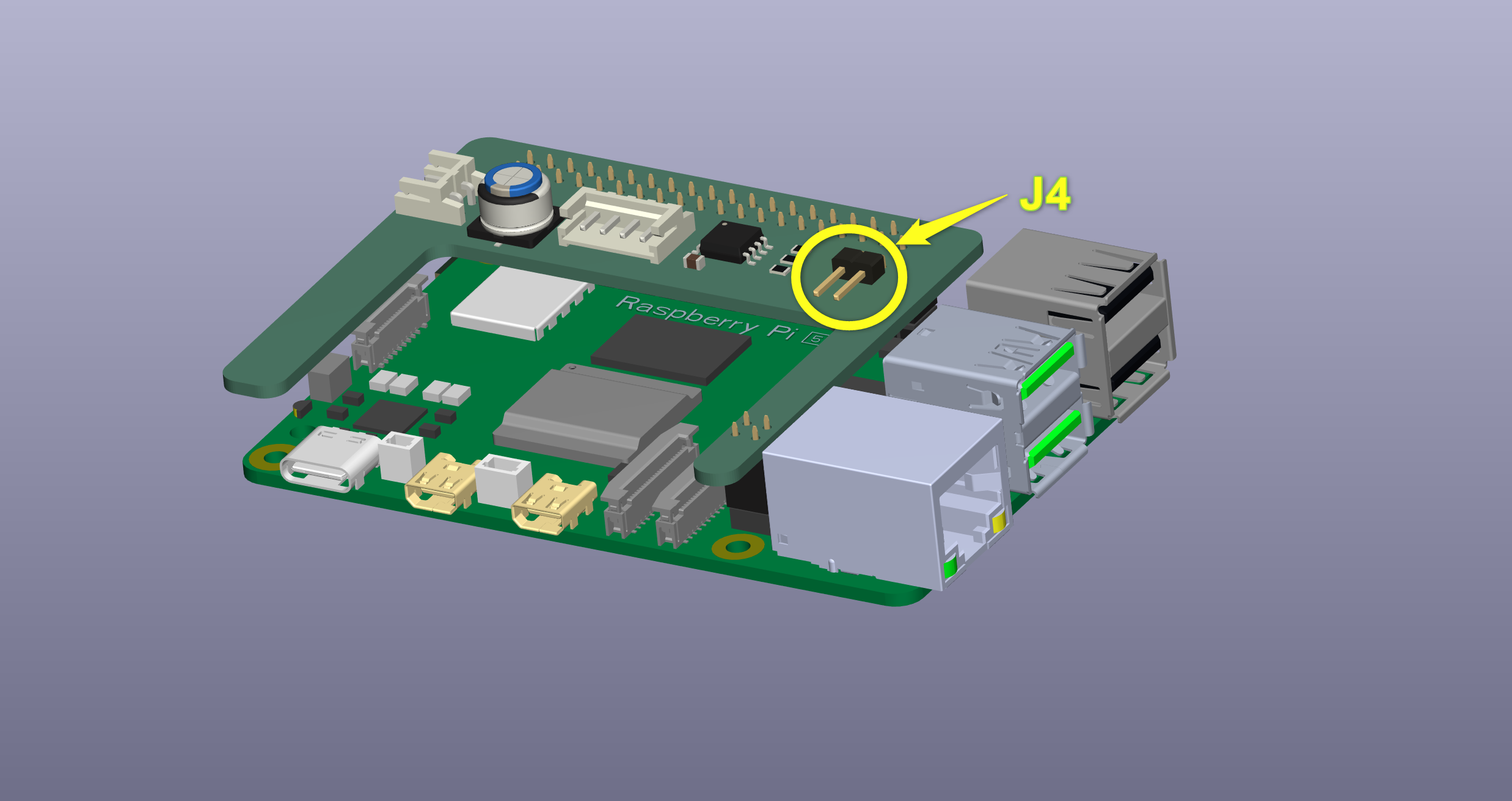
Use the prepared eep-file "../software/rpi5/hat/esd-power-hat.eep" from the ESD-Car_DIY-Bundle which could be flashed directly to the ESD-Power-Hats EEPROM (24c64 type):
rpi5@vehicle20:~ $ cd rpi5/hat/eeptoolsrpi5@vehicle20:~/rpi5/hat/eeptools $ sudo ./eepflash.sh -w -t=24c64 -f=esd-power-hat.eepContinue with answering "yes" to be sure to flash the EEPROM.
If this is not working see https://github.com/raspberrypi/utils/tree/master/eeptools to analyze with i2cdetect and check electrical state of soldered EEPROM.
To check if the flash procedure was successful you can have a look into the device tree after restart.
rpi5@vehicle20:~ $ cd /proc/device-tree/hat/rpi5@vehicle20:/proc/device-tree/hat $ cat vendor # To read the vendor name: ESD SW Teamrpi5@vehicle20:/proc/device-tree/hat $ cat product # To read the product name: ESD power HAT+ Resetrpi5@vehicle20:/proc/device-tree/hat $ cat product_id # To read the product ID: 0x1234Flashing Raspberry Pi Pico (Pico)
To operate the ESD Car 2.0 properly you need an microcontroller to read the inputs and control the Servos and stepper-motor.
The pre-compiled image for the Pico microcontroller is available under DIY ressource package "EcoSystemDemonstrator/pico".
The Image can be easily flashed to the target by connecting the Pico via USB to the PC and copying the UF2-Image file to the detected mass storage device "Pico-disc".
Press the "BootSel" button during connection of USB
"Pico-disc" is automatically mounted in OS (like a SD-Card)
Copy the UF2 onto the "Pico-disc"
Pico will reboot, unmount itself as a Mass Storage Device, and run the flashed code
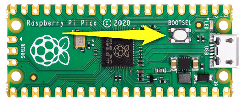
See page 36 "Load and run blink" from this reference https://datasheets.raspberrypi.com/pico/getting-started-with-pico.pdf