ESD Car 2.0 - System architecture and Introduction to the Software
Introduction
This page provides an overview of the main components of the ESD Car 2.0 and clarifies which are fixed and which open for development.
In general, this page provides following overviews:
Overview of HW components (computing units, sensors and actors)
Overview of SW and HW interfaces
Overview of SW resources (binary image and code repositories)
ESD Environment
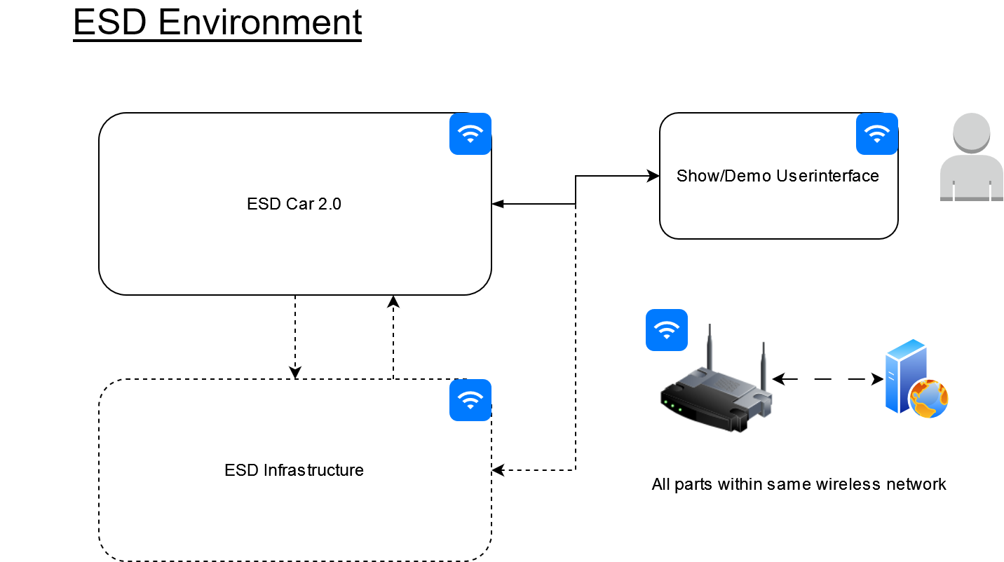
The ESD environment consists of 2 main parts: the ESD Car 2.0 itself and a user interface (e.g. Laptop) to control, configure and showcase the car and functions. They operate within one dedicated WiFi network, ideally reserved for the ESD.
Further ESD infrastructure is optional, depending on the additional use-cases which are not pre defined and if used, they shall be in the same network.
ESD Car
ESD Car Overview
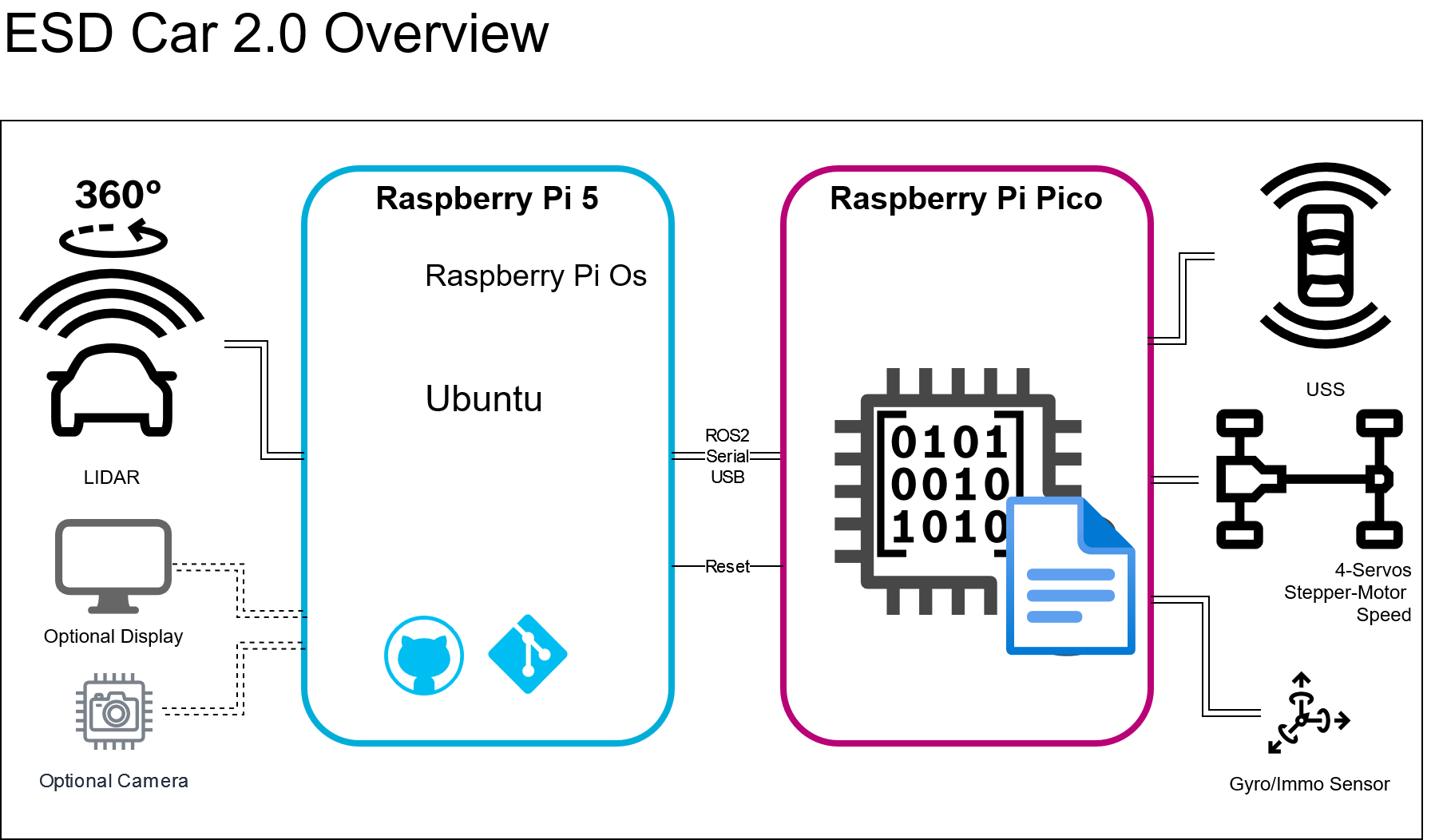
As shown in the figure below ESD Car 2.0 Overview, the ESD Car 2.0 is divided in 2 main parts:
Raspberry Pi 5 (RPI5) - hosts the ROS2 environment, the LIDAR-based car localization and all the high functions, like plan and control
Raspberry Pi Pico (Pico) - hosts the embedded control of the hardware components, that read the sensors and controls the actors to drive the car
The basic operation and interaction happens with interfaces of the ROS2 environment (ROS stands for Robot Operating System).
To get familiar with ROS2 it is recommended to go through the https://docs.ros.org/en/jazzy/Tutorials.html# , especially the chapters:
Raspberry Pi 5 (RPI5)
SW Resources
The SW Resources are divided in three parts:
Ubuntu with ROS2 standard binaries
ROS Workspace
Reserved space for implementation of use cases
For the first two, the corresponding artifacts are provided within the ESD Car DIY-Bundle.
Further details are explained next:
1) Ubuntu with ROS2 standard binaries - provided as builder script
|
Script purpose |
Link to user documentation |
location in ESD Car DIY-Bundle |
|
Ubuntu and ROS2 builder script |
.../software/ rpi5/ rpi_install.tar.gz |
|
|
EEPROM flash tools |
n.a. |
2) ROS Workspace - collects all resources for the ESD Car 2.0 ROS environment:
To learn how a ROS workspace works and how it is used check this tutorial - https://docs.ros.org/en/jazzy/Tutorials/Beginner-Client-Libraries/Creating-A-Workspace/Creating-A-Workspace.html
"Bosch developed scripts" all of them with MIT License:
Script purpose
Link to user documentation
location in
ESD Car DIY-Bundle1
Calibration of ESD Car
.../software/ rpi5/calibration
2
Basic implementation of receiver for odometry data
.../software/ rpi5/odometry
3
Basic implementation of Motion Command sender
.../software/ rpi5/motion_test
4
Ros2 custom messages
see below - Chapter - SW-Interfaces
.../software/ rpi5/ros_custom_msgs
Linked sub-modules
Module name
License
URL
1
micro-ROS-setup
Apache 2.0
2
micro-ROS-msgs
Apache 2.0
3
micro-ROS-Agent
Apache 2.0
4
rplidar_ros
BSD 2-Clause
Check the referenced git-repos for further information and usage. Especially for the "micro-ROS" environment on the Raspberry Pi Pico.
3) Your code for implementing your project! 🥳
For example, create a new package - like described here: https://docs.ros.org/en/jazzy/Tutorials/Beginner-Client-Libraries/Creating-Your-First-ROS2-Package.html
HW/SW Interfaces
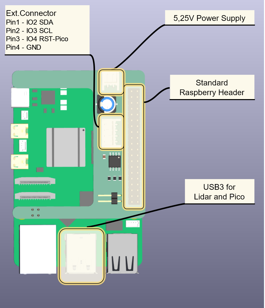
The following HW-interfaces of the RPI5 are used:
Power Supply via RPI5 Header board (5,2V Input)
External Connector - some Pins from the header are available for separate connection
Pin 3 is used to reset the Raspberry Pi Pico (IO4 pin of header)
Pin 1,2 are optional for I2C interface
Standard Raspberry Header
2 USB3 connectors are used
Lidar-Connection
Raspberry Pi Pico USB serial-com-port (for microROS2 client)
Raspberry Pi Pico (Pico)
The Pico environment is compatible with Platform.io framework and micro-ROS implementation. It controls the car based on the commands received from the ROS2 messages from RPI5 and give feedback to it.
It controls the corresponding IOs from the HW, and the interface of to RPI5 on HW-level is the serial-com via USB and the Reset-Line via GPIO.
The HW/SW is designed to be used on the Car20-Adapter board (See here for reference 2.2. Car2.0_AdapterBoard (Pico-Board)) , which carries the Pico and provides all interfaces on suitable connectors.
The Software is distributed via binary image file which can be flashed onto the Pico.
Raspberry Pi Pico - Functional Overview
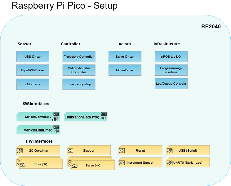
SW-Modules
USS-Driver
Reads the Ultrasonic sensor in the front and rear-side of the vehicle and evaluates the distance. Used to detect short term obstacles on the way, and stop movement.
Gyro/Imu-Driver
This driver reads the Gyro sensor of BMI088, which measures the orientation and rotation of the vehicle, and provides this information to other components for odometry and trajectory control.
This driver reads the Inertial Measurement Unit (IMU) sensor, which combines data from multiple sensors for acceleration to provide information about the vehicle's motion. IMU is currently not used in ESD2.0
Servo-Driver
The Servo-Driver controls the 4 Servo motors, which are responsible for precise angular movement of the vehicle.
Motor-Driver
Controls the Stepper Motor that drives the vehicle's front wheels to move forward and backward.
Trajectory Controller
This controller is responsible for controlling the vehicle's trajectory path, considering factors like desired speed, length and rotation.
Emergency stop
This module stops the vehicle if the safe-distance from USS sensors are undercut.
Odometry
Odometry provides data to the estimation of the vehicle's position and orientation based on sensor values from motion sensors, such as encoders on the wheels and the gyro.
Motion Actuator Controller
It is responsible for controlling the motion actuators in the vehicle, such as motors and servos, based on inputs from other components like the trajectory controller.
Infrastructure
Libraries and operating service.
SW-Interfaces
# Generaluint64 rostime # Timetamp from ROS environmentuint16 system_status # General system status (indicates e.g. test modes)# Odometryint32 kinematic_position_x # Perceived (kinematic) x position (mm)int32 kinematic_position_y # Perceived (kinematic) y position (mm)int16 kinematic_orientation # Orientation angle (mrad) - value range [0,6283)int32 velocity # Current velocity of the vehicle (mm/s)int32 yaw_velocity # Current angular velocity along yaw axis (mrad/s)int16 turn_cycle # Diameter of the current turning cycle in mm, positive values are mathematical positive rotations (counter clockwise), # negative values clockwise# Motion Controlint32 target_velocity # Target velocity of the vehicle (mm/s)int32 target_yaw_velocity # Target angular velocity along yaw axis (mrad/s)int8 current_throttle # Currently applied throttle by MotionControl [0,100]int8 current_steering # Currently applied steering by MotionControl [-100,100] (negative is left, positive is right)uint8 remaining_commands # Number of remaining commands INCLUDING the one that is currently executedint32 remaining_distance # Remaining distance to the target (mm)uint16 motion_control_status # Status of the motion control system (enum)uint16 current_command_id # ID of the currently executed command as given in the MotionCtrl msg## Waypoint navigationint32 current_waypoint_x # Current waypoint position x (mm)int32 current_waypoint_y # Current waypoint position y (mm)bool has_next_waypoint # Indicates if there is a next waypoint (in addition to current_waypoint)int32 next_waypoint_x # Next waypoint position x (mm) - only valid if has_next_waypointint32 next_waypoint_y # Next waypoint position y (mm) - only valid if has_next_waypoint# Sensor Datauint16 uss_front # Ultrasonic sensor reading in front (mm)uint16 uss_rear # Ultrasonic sensor reading in rear (mm)uint16 uss_left # Ultrasonic sensor reading on the left (mm)uint16 uss_right # Ultrasonic sensor reading on the right (mm)uint32 total_distance_traveled # Total distance the vehicle has traveled (mm)# Message sent from the RPi to uC to control which path to driveuint16 id # Command id: used for tracing of currently executed command in VehicleData msguint64 rostime # timetamp from ROS environmentuint32 velocity # target velocity in mm/suint32 arc_length # L = length of the arc in mmint32 angle # Theta = Angle at the center of the circle in mradbool override # Override flag; deletes the current and all pending arc commands if set; appends a subsequent arc to the execution list otherwise---#replies back to requesterbool accepted # true if the command has been accepted and queuedint8 current_queue_length # current length of the motion commands queueCalibrationData.msg
# Calibration data for steering/servosint8[4] mindeg # the minimal degrees which are possible for each one of the servosint8[4] maxdeg # the maximal degrees which are possible for each one of the servosfloat32[4] k # the k values for each wheel based on the calibration datafloat32[4] d # the d values for each wheel based on the calibration data# Calibration data for the stepper motorfloat32 stepperfactor # the factor for calibrating the actual speed of the stepper motor# Vehicle Parameters which are remotely related to calibration and also dimensions that affect calculationsuint16 wheelbase # defines the distance between the front and rear axleuint16 trackwidth # defines the distance between the middle of the left to the middle of the right wheelsfloat32 wheeldiameter # defines the diameter of the wheeluint16 wheelencoderpulsecount # the count of pulses that the encoder produces per revolution# Parameters for the Trajectory Controllerfloat32 throttle_kd_longfloat32 throttle_ki_longfloat32 throttle_kp_longfloat32 throttle_kd_shortfloat32 throttle_ki_shortfloat32 throttle_kp_shortfloat32 k_perpendicularfloat32 k_anglefloat32 switch_waypointfloat32 target_reached_thresholdfloat32 k_velocityfloat32 max_velocityfloat32 throttle_jerkActuatorTest.msg
# Message to control the Test- and Calibration procedureuint8 testmode # Trigger specific testmode in caruint8 calibrationmode # Trigger specific calibrationmode in carint8 throttle # Throttle value between -100 (backwards) - 0 (still) - 100 (forwards) %int8 steer # Steer value between 100 (turn left) - 0 (neutral) - -100 (turn right) %int16[4] servo_val # Single control for each servo (Front-right, front-left, rear-right, rear-left)int16 motor_steps # amount of steps for the stepper motor to driveint16 drive_lenght # drive given distance in mmint16 drive_speed # drive with given speed mm/secuint16 delete_caldata # codeword for deleting calibration data in EEPROM: 0xBABAActuatorTest.msg
# Feedback Message for the Test- and Calibration procedure# find reference in FlashRWStructs.hppuint32 struct_versionuint32 crcuint32 struct_size# servo valuesint8[4] min_degint8[4] max_degfloat32[4] kfloat32[4] d# motor valuesfloat32 stepper_cal_value# vehicle parametersuint16 wheel_baseuint16 track_widthfloat32 wheel_diameteruint16 wheel_encoder_pulse_count# trajectory controller parametersfloat32 throttle_kd_longfloat32 throttle_ki_longfloat32 throttle_kp_longfloat32 throttle_kd_shortfloat32 throttle_ki_shortfloat32 throttle_kp_shortfloat32 k_perpendicularfloat32 k_anglefloat32 switch_waypointfloat32 target_reached_thresholdfloat32 k_velocityfloat32 max_velocityfloat32 throttle_jerkHW/SW Interfaces
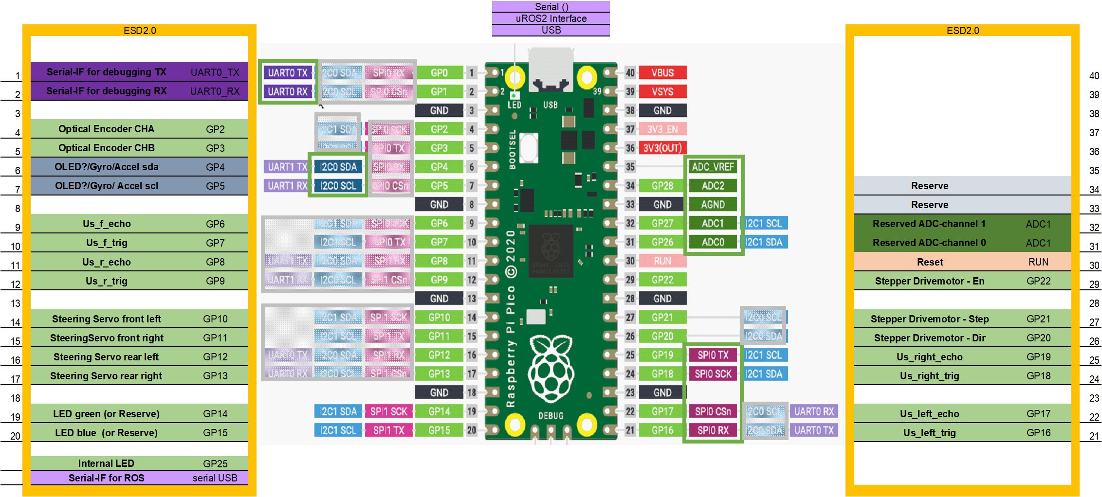
Based on Raspberry Pi Pico board with RP2040-Chip (more details in the official documentation).
I2C Gyro/Immo
The interface to the BMI088 sensor is an 3,3V I²C bus on Pin GP4 and GP5 (as I2C0)
The I²C bus is shared for an optional I²C OLED display.
USS
There are 4 Ultrasonic-sensors (USS) available on the ESD-Car-2.0. Each Sensor has one Input for an trigger Pulse, and one output for the echo signal (See general description for an HC-SR04 sensor type). Trigger signal is provided by Pico and echo signal is read in.
|
USS |
Pico-Pin |
|
Front |
GP6 / GP7 |
|
Rear |
GP8 / GP9 |
|
Left |
GP17 / GP17 |
|
Right |
GP19 / GP18 |
Stepper
The stepper motor is controlled with an separate driver PCB and 3 control lines:
|
Stepper Ctrl |
Pico-Pin |
|
En - Enable driver |
GP22 |
|
Step |
GP21 |
|
Dir - drive direction |
GP20 |
Servo
There are 4 servos to steer each wheel of the vehicle separately. Each servo is connected with an standard digital servo interface which is PWM modulated.
|
Servo |
Pico-Pin |
|
Front left |
GP10 |
|
Front right |
GP11 |
|
Rear left |
GP12 |
|
Rear right |
GP13 |
Reset
With the RUN pin of the Pico a reset could be triggered. This pin shall be connected to the RPI5 Header board (or GPIO4), so that the RPI5 can trigger a reset to the Pico.
Increment-Sensor (Odo-Sensor / optical encoder)
For generation of the odometer for the car a optical encoder is used within the front wheel. It will generate increment pulses during movement of the wheel. 2 Channels are used to detect direction of driving.
|
Sensor |
Pico-Pin |
|
Opto CHA |
GP2 |
|
Opto CHB |
GP3 |
USB Serial
The USB interface of Pico is used as serial port at 115200 baud to communicate with the RPI5 on micro-ROS protocol.
UART0
The UART0 of the Pico is used to print debug and log messages via serial port at 115200 baud.